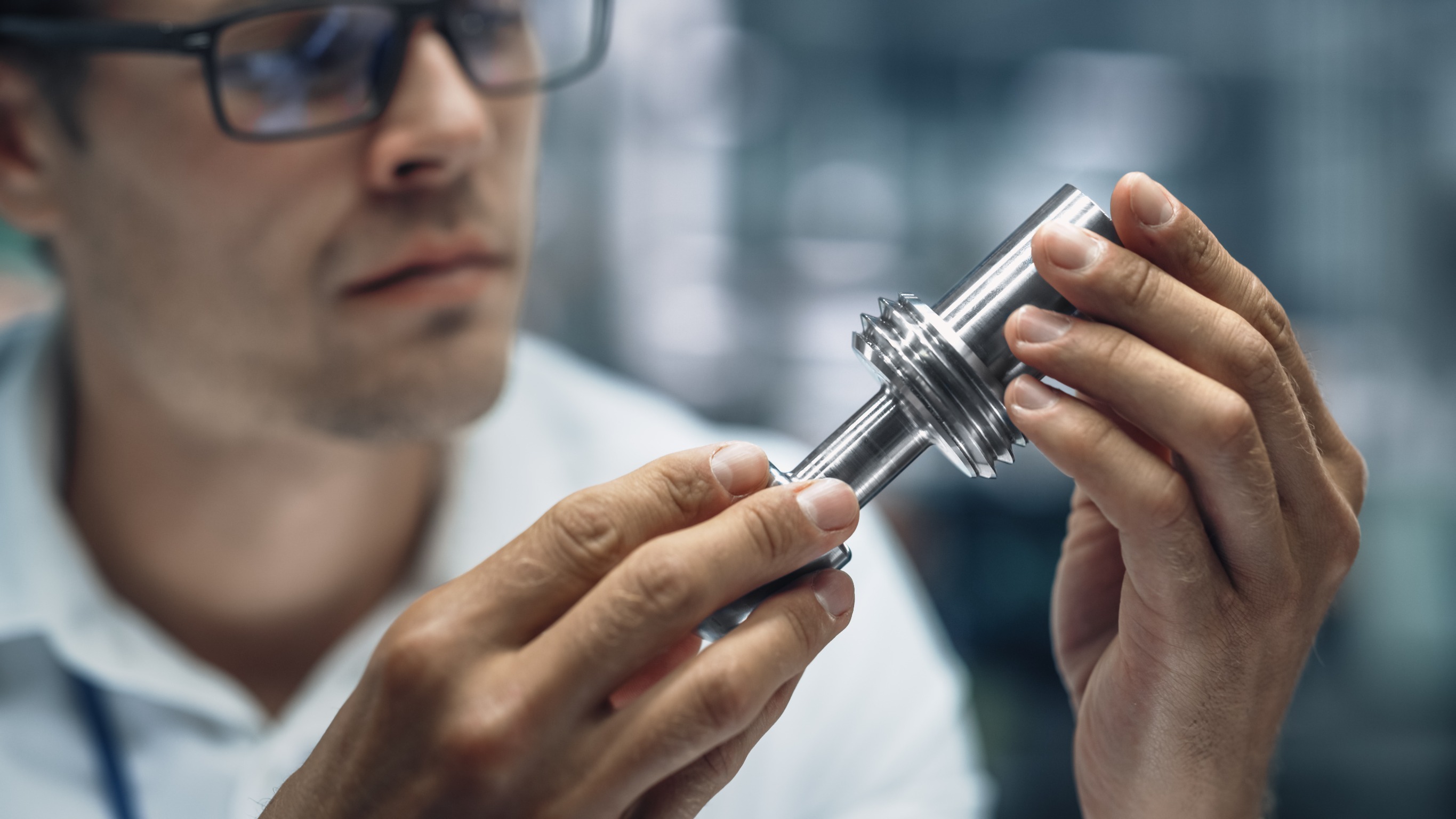
Lathe machines are used to remove excess material from a workpiece to give the workpiece the desired shape and size. Machining process designed for precision machining of relatively hard materials.
What is a Lathe? Basic Knowledge of Lathes
A lathe is an ancient tool. Developed as early as around 1300 BC, when not many parts were developed other than the headstock and tailstock. But during the Industrial Revolution, metalworking lathes evolved into heavier machines with thicker, more rigid parts.
Between the 19th and 20th centuries, electric motors were replaced with spools as a power source. Then in 1950, the servo mechanism was applied to the control of machine tools such as CNC lathes, and direct CNC machine tools. Lathes are the most versatile of all standard machines. Manually controlled machines exist just like CNC machines, and even more machining operations are performed with the help of manually operated feed mechanisms on lathes.
A lathe is a machine tool used to remove metal from a workpiece to obtain the desired shape and size. Lathes are used for metalworking, wood turning, metal spinning, thermal spraying, glass processing, and parts recycling. Various other operations that can be performed with the help of a lathe include grinding, cutting, knurling, drilling, and deforming, and these tools are used to create objects that are symmetrical about an axis of rotation. A lathe is a tool that rotates a workpiece about its axis to perform various operations, such as cutting, grinding, knurling, drilling, or deforming, facing, turning, and using the rotation of a tool that is applied to the workpiece to create objects that are symmetrical about the axis. They were originally designed for machining metals; however, with the advent of plastics and other materials, and their inherent versatility, they are used in a wide range of applications and a wide range of materials.
A lathe is a machining tool primarily used to shape metal or wood. It works by rotating the workpiece around a stationary tool. The main use is to remove unwanted parts of the material, leaving beautifully shaped workpieces. The function of a lathe is to remove metal from the workpiece in the form of chips by mounting the workpiece rigidly on the machine tool spindle and rotating it at the desired speed, and the cutting tool feeds the workpiece longitudinally or transversely to work to the desired shape and size.
Correct orientation of the lathe:
The headstock should be on the left and the tailstock should be on the right. The headstock is where the main action takes place. This is where the power of the motor is applied to the workpiece. Part of its purpose is to hold the spindle, so you should see that here too. The motor is located on the left side of the bottom of the bed near the headstock. It's usually some type of electric motor, but lathes can also have hydraulic motors.
What are the Parts of the Lathe? Learn about Lathe Parts and Their Functions
-
Headstock:
The headstock is located on the left side of the bed and is where the drive mechanism and electrical mechanism of the lathe machine are located. Accessories mounted on the headstock spindle include jaw chucks, collet chucks, faceplates, magnetic chucks, and more. A separate variable speed gearbox is placed under the headstock to reduce the speed to provide different feed rates for the automatic lateral movement of the threads and slides. The feed rod is used for most turning operations and the lead screw is used for thread cutting operations.
- The spindle box fixes the workpiece on the spindle nose with external thread and internal Morse taper, which is used to fix the center of the lathe. It rotates at different speeds through a bevel or full gear drive. The entire spindle has a hole for handling long stick jobs.
- The headstock transmits the power from the main shaft to the feed rod, lead screw, and thread cutting mechanism.
-
Bed:
The Bed is the base of the lathe, cast in one piece from semi-steel (chilled cast iron). The bed consists of two heavy metal slides running longitudinally with rails or V-shapes and rigidly supported by cross loops.
- Bed has enough rigidity and good damping capacity to absorb vibration.
- Bed can prevent deformation caused by cutting force.
- Bed supports the headstock, tailstock, bracket, and other parts of the lathe.
-
Tailstock:
The tailstock is located on the right side above the bed.
- Tailstock supports the long end of the work to maintain and minimize sagging.
- Tailstock has tools for performing different operations like drilling, reaming, tapping, etc.
- Tailstock A small taper for long work by offsetting the tailstock.
-
Carriage:
When machining is complete, the carriage is used to support, guide, and feed the tool. The Carriage installation includes saddle, cross-slide, compound rest, toolpost, and apron.
- The Carriage shall remain mobile and control the cutting tool.
- Carriage provides rigid support for the tool during operation.
- Carriage transmits the power from the feed rod to the cutter through the baffle mechanism for longitudinal cross feed.
- Carriage simplifies thread cutting operations with the help of a lead screw and half nut mechanism.
- It is used for longitudinal feed-through carriage movement, transverse cross-slide movement, and angular feed-through top slider movement.
-
Saddle:
The Saddle is made from an H-shaped casting and has V-shaped rails and flat rails for mounting it on the bed rails.
-
Cross-slide:
Assembled on the top of the saddle, there is a T-slot on the top of the cross slide.
-
Compound rest:
Support tool holders and cutting tools in different positions. It can be rotated in any desired position on the horizontal plane. Requires turning angles and boring short tapers.
-
Tool post:
It is the topmost part of the bracket and is used to hold various cutting tools or tool holders. Commonly used tool holders are ring and rocker tool posts, squarehead tool posts, and quick-change tool posts.
-
Apron:
An apron is a house of the feed mechanism. It is fastened to the saddle and hangover in front of the bed.
-
Lead Screw:
Lead screws are also known as power screws or translation screws. It converts rotational motion to linear motion. Lead screws are used for thread cutting operations in lathe machine tools.
-
Feed rod:
The feed bar is used to move the trolley from left to right and from right to left.
-
Chuck:
Chucks are used to hold workpieces securely. Common chucks include 3 jaw self-centering chucks and 4 jaw independent chucks.
-
Main spindle:
The spindle is a hollow cylindrical shaft through which long jobs can pass. It is designed so that the spindle does not deflect when thrust from the cutting tool is generated.
-
Leg:
The legs carry the full load of the lathe machine and transfer it to the ground. The outriggers are firmly fixed on the floor by the anchor bolts, which support the stable support of the machine.
How Many Types of Lathes are There? Characteristics of Different Types of Lathes
-
Center or engine lathe:
Center lathes or engine lathes are the most widely used lathes and are often present in every shop. Operations such as turning, facing, grooving, knurling, threading, etc., are performed on center or engine lathes. The lathe has all parts such as bed, saddle, headstock, tailstock, etc. The headstock of the lathe is rigid and the tailstock is movable, which is further used to support operations such as knurling. With its feed mechanism, the tool can be easily fed in both longitudinal and transverse directions. The center lathe is driven by a gear mechanism or a pulley mechanism. There are three types of drive mechanisms, namely belt drive, motor drive, and reducer type.
-
High-speed lathe:
High-speed lathes, also known as wood lathes, process at high speeds, ranging from 1200 to 3600 RPM. The headstock spindle rotates at a very high speed. The part has a headstock and tailstock, but no center or lathe-like feed mechanism, and the feed is manually operated. High-speed lathes are commonly used for turning, centering, polishing, and machining wood.
-
Winch and turret lathes:
Winch and turret lathes are used in series production and are an improved version of engine lathes. Where capstan and turret lathes are used to perform their sequence of operations on a workpiece, there is no substitute operation performed on this machine. The machine is provided by a hexagonal turret head instead of a tailstock, in which multiple operations (turning, facing, boring, reaming) are performed in sequence after the turret is rotated after each operation, without the need for manual tool changes. Three tool columns are included, so require more floor space than other lathes. Winch and turret lathes are only used for large jobs. The main advantage of using a winch and turret lathe is that even less skilled operators can get the job done.
-
Tool room lathe:
Tool room lathes operate at speeds up to 2500 rpm. The parts are almost identical to the engine lathe, but the parts are made very precisely and should be in the correct order, as this lathe is used for highly precious jobs with very tight tolerances. Mainly used for grinding, tooling, scale, and machining jobs where precision is required.
-
Bench lathe:
The bench lathe is mounted on the table. This type of lathe is small and used for very small precision jobs. It has all the similar parts of an engine lathe and a high-speed lathe.
-
Automatic lathe:
Automatic lathes work: automatically. Automatic lathes are used for mass production. Some mechanisms are responsible for the automation of this. There is no need to manually change the tool as it changes automatically. The advantage is that one operator can handle more than 4 to 5 machines at a time. Automatic Lathes Lathes are high-speed and heavy-duty.
-
Special purpose lathes:
Specialized lathe machines perform special types of operations that cannot be performed on standard machines and other machines. Known for heavy-duty production of identical parts. Some examples of special lathes include vertical lathes, wheel lathes, T-type lathes, multi-spindle lathes, production lathes, copy or tracking lathes, and the like.
- Wheeled lathes are used to machine journals and rail rods and to turn threads on locomotive wheels.
- T-type lathes are used for machining jet engine rotors. The axis of the bed is at a right angle to the axis of the main shaft of the headstock, forming a T shape.
-
CNC lathe:
CNC lathe stands for Computer Numerical Control. It is widely used as a lathe due to its fast and accurate work and is one of the most advanced types of lathes available. CNC lathes use a computer program to control the machine. Once the program is programmed into the computer, it will start running with very high speed and accuracy. Even a pre-planned programmed machine, once the code is set for various operations, can start operating the next time without changing the code. After the initial setup, semi-skilled workers can easily operate it. Suitable for high volume production such as winches and turrets, but without a programmed feed system. The parts made by these lathes are precise in terms of dimensional tolerances.
Advantages of CNC lathe processing:
- It is suitable for the center volume production of frequently changing production items in the work.
- Installation and processing time can be reduced.
- Tool costs are lower due to the ideal design of cutting speeds and feeds.
- Good product and high reliability.
- A lot of pre-work time can be avoided.
- Can reduce inspection costs.
- The operator does not need to have advanced technology.
- It can avoid the use of special molds, fixtures, etc., saving processing time.
What are the Operations Performed by the Lathe?
-
Centering:
When the workpiece is to be held between the two centers, a centering operation is used to create a tapered hole in the surface of the workpiece for bearing support in the center of the lathe.
-
Facing:
The end face operation is to make the end of the workpiece produce a smooth surface with a certain length of the operating axis or workpiece.
-
Turning:
The operation of removing excess material from a workpiece to produce a conical or cylindrical surface. There are several types of turning operations, including the following:
- Straight Turn: Straight turn is done to create a cylindrical surface by removing excess material from the workpiece.
- Shoulder: Shoulder turning has different diameters to form steps from one diameter to another.
- Rough turning: Rough turning is the process of removing excess material from a workpiece in the shortest possible time by applying high feed rates and heavy cutting depths. The depth of cut is approximately 2 to 5 mm, and the feed rate is 0.3 to 1.5 mm/rev.
- Finish turning: Finish turning operations require high cutting speeds, minimal feeds, and small depths of cut to produce smooth surfaces. The depth of cut is approximately 0.5 to 1 mm and the feed rate is 0.1 to 0.3 mm/rev.
- Taper Turning: Taper is defined as the uniform decrease or increase in the diameter of the workpiece with its length. The operation of producing a tapered surface of decreasing diameter from a cylindrical workpiece is called taper turning.
-
Chamfering:
Chamfering is used to chamfer the end of the work to remove burrs, give a better look, and allow the nut to go into the bolt. Taper turning operations are performed after thread cutting, knurling, and rough turning.
-
Knurling:
Knurling is the process of creating a rough surface on a workpiece to provide effective clamping. The knurled tool is securely attached to the tool holder and pressed against the rotating workpiece, leaving a replica of the tool on the surface of the workpiece.
-
Thread cutting:
The operation of creating a helical groove on a cylindrical or conical surface by longitudinally feeding the tool as the workpiece rotates between two centers.
-
Drilling:
Drilling is an operation in which holes are made in a workpiece by drilling. In this operation, the workpiece is rotated at the turning speed on the lathe shaft and the drill is mounted on the tailstock spindle. And the tailstock is moved to work by manual feed.
-
Boring:
Can enlarge the diameter of the existing hole on a job by turning inside with some farm tool known as a boring tool.
-
Reaming:
Reaming is the operation of dimensioning or finishing a drilled hole to the desired size through a tool called a reamer.
-
Spinning:
In the spinning operation, the sheet metal work is clamped between the forming machines, and the center of the tailstock rotates with the forming machine at high speed. The oval head forming tool rigidly fixed to the special tool holder presses the workpiece against the periphery of the former. It is a chip less machining process.
-
Tapping:
Use a tapping operation to create internal threads in a hole with a tool called a tap.
-
Parting off:
Slitting is the operation of cutting off a bar-shaped workpiece after completing the machining process.