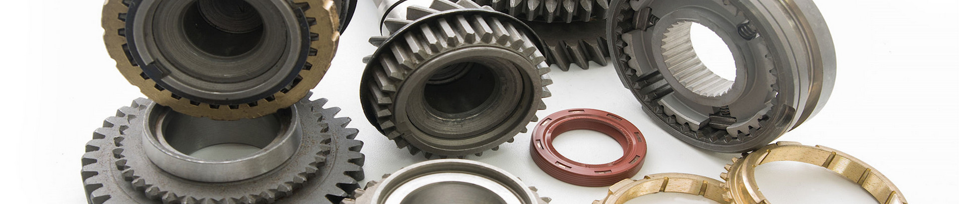
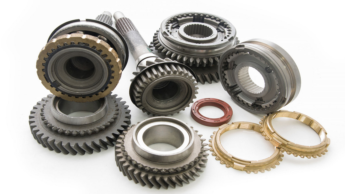
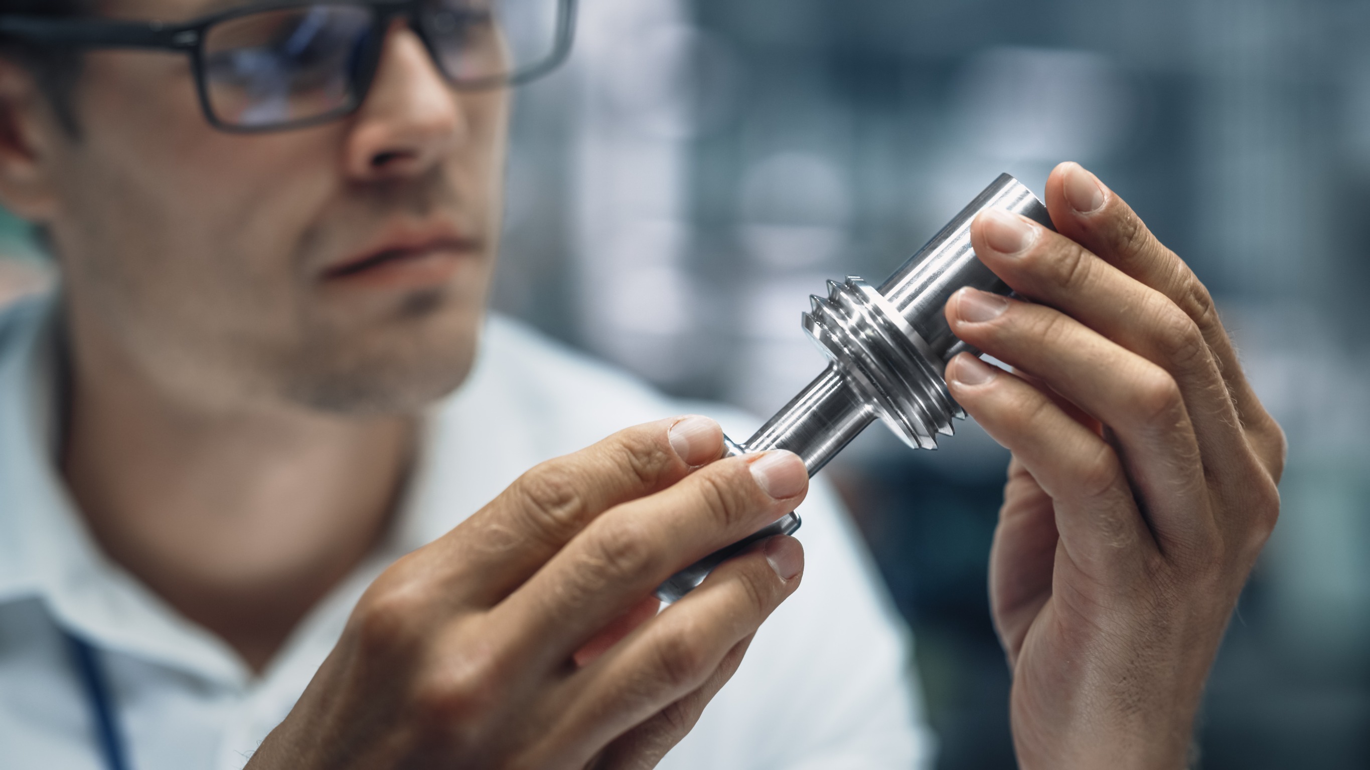
A worm gear is a gear consisting of a shaft with a helical thread that meshes with and drives the gear.
What is Worm Gear?
A worm gear is an ancient gear, a variation of one of six simple machines. A worm gear is a screw that interfaces with what looks like a standard spur gear with slightly angled and curved teeth. It changes the 90-degree rotational movement and the plane of motion is changed by the position of the worm on the worm gear. They usually consist of a steel worm and a brass wheel. A worm drive is a transmission that transmits motion and power between two axes that are interlaced in space.
How Does the Worm Gear Work?
An electric motor or engine applies rotational power through a worm. The worm rotates against the wheel, and the helicoid pushes against the teeth of the wheel. The wheels are pushed against the load. The worm drive refers to the deceleration transmission with the worm as the main action. When the reverse stroke is not self-locking, the worm gear can also be used as the main action to speed up the transmission. The worm drive is composed of a worm and a worm gear, and the worm is generally the active part. Worms, like threads, can be divided into right-handed and left-handed, which are called right-handed worms and left-handed worms, respectively.
Structure Type of Worm Gear:
- Integral type: Used for cast iron and bronze worm gears with small diameters.
- Ring gear press-fit: The hub is cast iron or steel, and the rim is bronze.
- Bolt connection type: The wheel rim and the hub adopt reamed holes and are connected by bolts. This structure is easy to assemble and disassemble.
- Casting type
What is Worm Gear Used for?
- High Reduction Ratio: Worm gears can achieve huge reduction ratios effortlessly - all that needs to be done is to increase the circumference of the wheel. So, it can be used to greatly increase torque or greatly reduce speed. It often takes multiple reductions on a traditional gear set to achieve the same level of reduction as a single worm gear, which means fewer moving parts and points of failure for worm gear users.
- Impossibility to reverse the direction of power: Due to the friction between the worm and the wheel, it is almost impossible for the wheel applying force to initiate the worm to move. On a standard gear, the input and output can turn independently once sufficient force is applied. This necessitated the addition of a backstop to the standard gearbox, further increasing the complexity of the gear set.
Worm Drive Features:
- Large transmission ratio and compact structure. The number of worm heads is represented by Z1 (generally Z1=1~4), and the number of worm gear teeth is represented by Z2. It can be seen from the transmission ratio formula I=Z2/Z1 that when Z1=1, that is, the worm is single-headed, and the worm must turn Z2 to turn the worm wheel for one turn, so the transmission ratio can be obtained. Generally, in power transmission, take the transmission ratio I=10-80. In the indexing mechanism, can reach 1000. Such a large transmission, such as gear transmission, needs to adopt multi-stage transmission, so the worm transmission has a compact structure, small in size, and is lightweight.
- The transmission is smooth and noiseless. Because the worm tooth is a continuous and uninterrupted helical tooth, it is continuous when meshing with the worm gear teeth. The worm tooth does not enter and exit the meshing process, so the work is stable, and the impact, vibration, and noise are relatively small.
- Self-locking. When the helix angle of the worm is small, the worm can only drive the worm gear, but the worm gear cannot drive the worm to rotate.
- The efficiency of worm transmission is low. It is generally believed that the efficiency of worm transmission is lower than that of gear transmission. Especially for self-locking worm drives, the efficiency is below 0.5, and the general efficiency is only 0.7-0.9.
- The calorific value is large, the tooth surface is easy to wear, and the cost is high.
Worm Gear Transmission Efficiency:
Any mechanical movement is accompanied by some losses, and of course, the operation of gears is no exception. Most of these losses are friction losses, such as bearing friction, the viscosity of lubricating oil and stirring loss, and friction loss on the tooth surface of the gear itself. Due to the friction loss of the bearing and the stirring loss of the lubricating grease, it is difficult to obtain the loss data. From the standpoint of the gear, will discuss the friction loss of the tooth surface of the gear itself.
Since the transmission efficiency of general spur gears, helical gears, and bevel gears is above 95%, if the tooth surface is ground again, the transmission efficiency can even be as high as 99%, so there is not much scope for calculation or discussion. However, the transmission efficiency of the worm gear transmission varies from the lowest 30% to the highest 90% depending on the assembly, load, lubrication, speed, tooth surface smoothness, material, lead angle, and several teeth.
Why Not Use Worm Gear?
One particularly obvious reason people don't choose worm gears over standard gears is because of lubrication. The movement between the worm and the gear face is purely sliding. No rolling parts contact or interact with the teeth. This makes them relatively difficult to lubricate. The required lubricants are often of high viscosity (ISO 320 or higher) and therefore difficult to filter, and are often specialized for their purpose, requiring a product on-site specifically for that type of equipment.
Worm Gear Lubrication:
The main problem with a worm gear is how it transmits power. The helical motion allows a large reduction in the space required in a relatively small space if standard helical gears are used. This spiraling motion also leads to an incredibly problematic condition as the dominant mode of power transmission. This is often referred to as sliding friction or sliding wear. For a typical gear set, power is transferred at the peak load point on the teeth, at least under rolling wear conditions. Sliding occurs on both sides of the apex but at relatively low speeds.
For worm gears, the sliding motion is the only power transmission. As the worm slides over the gear teeth, it slowly wipes off the lubricating oil film until there is no lubricating oil film left, and as a result, the worm rubs against the metal of the wheel in boundary lubrication. As the worm surface leaves the wheel surface, it picks up more lubricant and starts the process anew on the next revolution. Rolling friction on a typical gear tooth requires a little lubricating film to fill the space and separate the two parts. Since sliding occurs on both sides of the gear tooth tips, a slightly higher viscosity lubricant is required to overcome this load than is strictly required for rolling wear. Sliding occurs at relatively low speeds.
The worm on the worm set gear turns, and as it turns it compresses the load applied to the wheel. The only way to prevent the worm from touching the wheel is if the film thickness is large enough so that it doesn't wipe off the entire tooth flank before that part of the worm leaves the load zone. This situation requires a special lubricant. Not only does it have to be a relatively high viscosity lubricant, but the higher the load or temperature the higher the viscosity has to be, it has to have some way to help overcome the slip conditions present.
Viscosity:
Viscosity is the main factor preventing the worm from contacting the wheels in the worm gear set. While the load and size of the gear dictate the lubricant required, ISO 460 or ISO 680 are fairly common and ISO 1000 is not unheard of. If you've ever tried to filter viscosities in this range, you know it's problematic, as the filters or pumps you have on-site likely aren't the right size or rating to perform properly. Therefore, you may need specific pumps and filters for this type of equipment. Viscous lubricants require slow-running pumps to prevent the lubricant from activating the filter bypass. It will also require a high surface area filter to allow the lubricant to flow through.
What is Worm Gear Metallurgy?
The most common worm gears are made of brass wheels and steel worms. This is because the brass wheel is usually easier to replace than the worm itself. The wheel is made of brass as it was designed for sacrifice. With the two surfaces in contact, the worm is slightly safer to wear due to the softer wheel, so most of the wear occurs on the wheel. Oil analysis reports for such units almost always show some level of copper and a small amount of iron.
This brass wheel introduces another problem to the worm gear's lubrication equation. If EP gear oil is placed in the sump of a worm gear with a brass wheel, and the temperature is high enough, the EP additive will be activated. In ordinary steel gears, this activation creates a thin oxide layer on the surface that helps protect the teeth from shock loads and other extreme mechanical conditions. However, on brass surfaces, the activation of extreme pressure additives can lead to severe sulfur corrosion. In a short period, can lose most of the wheel's load surface and cause significant damage.
Other Materials:
- Steel Worm and Steel Worm Gear: This application doesn't have the EP complications of brass gears, but there's no room for error in a gearbox like this. Restoring a worm gear set with this metal combination is usually more expensive and time-consuming than using a brass/steel worm gear set. This is because the material transfer associated with the failure made both the worm and the wheel unusable in the rebuild.
- Brass Worms and Brass Worm Gears: This application is most likely to be found under moderate to light loads, as brass can only withstand lower loads. Lubricant selection is flexible for this combination of metals due to the lighter loads, but due to the yellow metal, one still has to consider the additive limitations regarding EP.
- Plastic on metal, plastic on plastic, and other similar combinations: This is often found in relatively light-loaded applications, such as robotics and automotive components. Lubricant choice depends on the plastic used, as many plastic varieties will react with hydrocarbons in conventional lubricants, requiring silicon-based or other non-reactive lubricants.
Although worm gears always have some complexity compared to standard gear sets, they are easily an efficient and reliable device. With a little attention to setting and lubricant selection, a worm gear can provide as reliable a service as any other type of gear set.