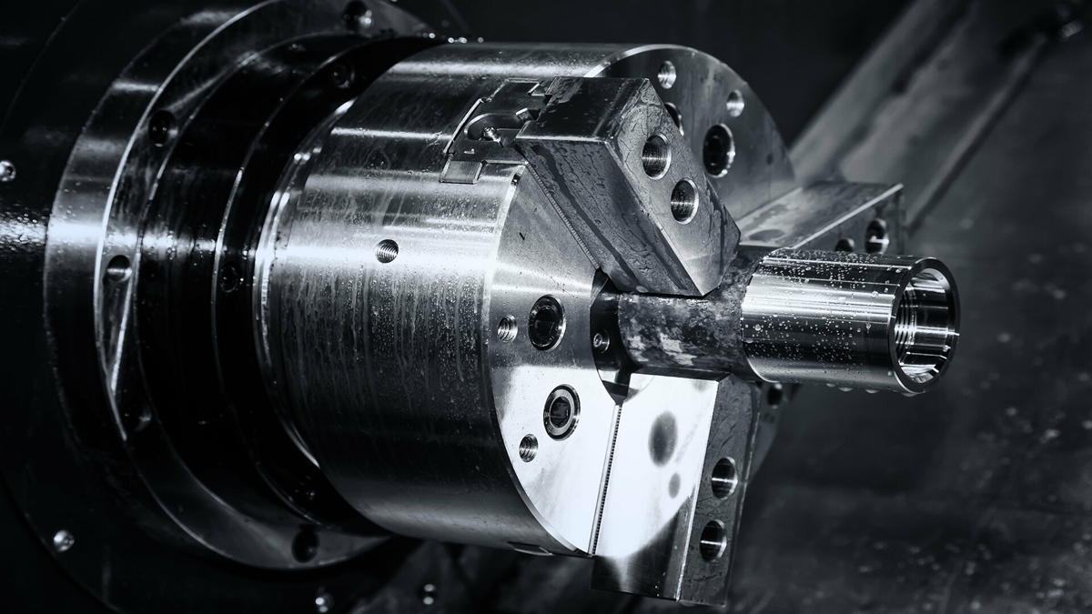
The advantage of the gearbox is that it can accurately control the speed of the main shaft without excessively high main shaft speed, belt friction consumption, and slippage. Because the main shaft is placed horizontally, it is also called a horizontal lathe.
What is Horizontal Lathes?
A horizontal lathe is a machine tool that mainly uses a turning tool to turn a rotating work piece. Drills, reamers, reamers, taps, dies and knurling tools can also be used on the lathe for corresponding processing.
A lathe is a machine tool that mainly uses a turning tool to turn a rotating work piece. Drills, reamers, reamers, taps, dies and knurling tools can also be used on the lathe for corresponding processing. The main components are spindle box, exchange gearbox, feed box, slide box, tool holder, tail stock, smooth screw, lead screw, bed, bed foot, and cooling device.
Features of the horizontal lathe:
- The bed, foot, oil pan, etc. of the lathe adopt an integral casting structure with high rigidity and good shock resistance, which is in line with the characteristics of high-speed cutting machine tools.
- The head stock adopts the structure of three bearings, all of which are tapered roller bearings. The spindle is easy to adjust, with high rotation accuracy and good accuracy retention.
- The feed box is equipped with a metric-inch thread conversion mechanism, which is convenient and reliable for the selection and conversion of thread types.
- There is a cone clutch safety device in the slide box to prevent damage to the parts after the automatic knife is overloaded.
- The lathe machine tool is equipped with a four-station automatic feed mechanical stop device in the longitudinal direction. By adjusting the longitudinal position of the cam on the stop lever, the required length of the work piece can be set to realize the longitudinal dimension processing of the parts.
- The tail stock is equipped with a variable speed device, which can meet the needs of drilling and reaming.
- The design of the lathe lubrication system is reasonable and reliable. The head box, feed box, and slide box are all internally splash lubricated, and line pumps and plunger pumps are added for automatic forced lubrication of special parts.
Structural components of the horizontal lathe:
- Gearbox: The gearbox is used to change the speed of the main shaft. It is mainly composed of a transmission shaft and a transmission gear. By manipulating the gear or clutch position outside the gearbox and the main shaft box, the main shaft can obtain 12 different speeds. The reversal of the spindle is achieved by the reversal of the motor.
- Spindle box: The spindle box is used to support the spindle and make it rotate at various speeds; the spindle is hollow, which is convenient to pass through long work pieces; the tip of the spindle can be installed with a tapered hole, or the front end of the spindle can be used The chuck and dial are installed on the conical surface to facilitate clamping of the work piece.
- Hanging wheel box: The hanging wheel box is used to match gears with different numbers of teeth to obtain different feed rates. Mainly used for turning different kinds of threads.
- Feed box: The feed box is used to change the feed amount. The main shaft is transferred to the movement of the feed box through the gearbox, and the meshing position of the sliding gear in the feed box can be changed by moving the shift handle so that the polished rod or the screw rod can obtain different speeds.
- Slide box: The slide box is used to change the rotation of the smooth rod and the lead screw into the automatic feed motion of the tool post. Smooth screws are used for general turning, and lead screws are only used for threading. There is an interlocking mechanism in the slide box so that the two cannot be used at the same time.
- Tool post: The tool post is used to clamp the turning tool and make it make longitudinal, lateral, or oblique feed motion.
The tool holder consists of the following parts:
- Bed saddle: It is connected with the slide box and can be moved longitudinally along the bed rails, with horizontal rails on it.
- Middle slide: It can move horizontally along the guide rail on the saddle.
- Turntable: It is fastened with the middle slide plate with screws, and it can be turned at any angle in the horizontal plane by loosening the screws.
- Small skateboard: It can move a short distance along the guide rail on the turntable; when the turntable is deflected by a certain angle, the small skateboard can be used to feed diagonally to facilitate the tapered surface.
- Square tool holder: It is fixed on a small sliding plate and can clamp four turning tools at the same time; loosen the locking handle, you can rotate the square tool holder and replace the needed turning tools to the working position.
- Tail stock: The tail stock is used to install the rear center to support the work piece, or install drills, reamers, and other tools for hole processing. The structure of the tail stock is shown in Figure 3. It is mainly composed of a sleeve, a tail stock body, and a base. By turning the hand wheel, the sleeve can be adjusted to a certain distance, and the tail stock can also be moved to the required position along the bed rail to meet the requirements of different work piece processing.
- Bed: The bed is fixed on the legs of the bed. The bed is the basic support of the lathe. The function of the bed is to support the main components and keep them in an accurate relative position during work.
- Lead screw: The lead screw can drive the large carriage to move longitudinally for turning threads. The lead screw is one of the main precision parts in the lathe. Generally, the lead screw is not automatically fed to maintain the precision of the lead screw for a long time.
- Light bar: Light bar is used to transfer motion during a motorized feed. The movement of the feed box can be transmitted to the slide box through the light bar so that the tool holder can make longitudinal or horizontal feed movement.
- Machine joystick: The machine joystick is the control mechanism of the lathe. There is a handle on the left end of the joystick and the right side of the carriage box. The operator can easily manipulate the handle to control the main shaft of the lathe to rotate forward, reverse, or stop.
The transmission system of the horizontal lathe:
The horizontal lathe is driven by a rack and pinion: the power output by the motor is transmitted to the main shaft through a gearbox through a belt-drive, and the handle positions outside the gearbox and the main shaft box are changed to obtain different gear sets to mesh, thereby obtaining different main shaft speeds. Taihao Machinery is the company's main products with electromechanical spindles for tools, rotary thimbles, lead screws, shaft machining, CNC lathe machining, tool holders, chucks, and chuck adapters. The spindle drives the work piece to rotate through the chuck. At the same time, the rotation movement of the main shaft is transmitted to the slide box through the reversing mechanism, exchange gears, feed box, and smooth rod (or lead screw), so that the slide box drives the tool post to move linearly along the bed.
Braking device of the horizontal lathe:
The main function of the braking device of the CNC horizontal lathe is to be used in the parking process of the lathe, to overcome the rotational inertia of the moving parts in the head stock, and to control the spindle to stop rotating quickly to shorten the auxiliary time and to install the brake of the horizontal lathe.
The CNC horizontal lathe uses a brake band brake, which is mainly composed of a brake wheel, a brake band, and a lever. The brake wheel in the brake device is a steel disc splined with the shaft. The steel brake band is fixed on the inner side with a layer of steel mesh asbestos to increase the coefficient of friction. One end is linked to the spindle box and the other end is fixed to At the upper end of the lever, the brake band of the horizontal lathe can be adjusted tightly, and it can be placed and adjusted by directly loosening the spiral connecting the brake band and the spindle box. When the CNC horizontal lathe is adjusted properly, the brake band can be released when the main shaft rotates, but when the clutch is in the released state and the horizontal lathe is stopped, the brake band will hold the brake wheel to realize the rapid stop of the main shaft, the brake is reached.
Operating rules and precautions for horizontal lathes:
- Check whether all parts are in good condition before driving. After the cold car is started, the vertical shaft should be idling at a low speed for 2-20 minutes. It is especially important to use lubricating oil to spread everywhere in winter. Wait for the lathe to work normally.
- When the vertical shaft needs to change speed during work, it must stop and change speed.
- To ensure the precision of the screw rod, it is not allowed to use the long screw rod for automatic feeding except for threading.
- It is not allowed to knock on the chuck or the bed guide rail to correct the work piece or tools on the bed surface.
- When the pad clamp is used to correct the heavier work piece, a wooden board should be used to protect the bed surface. If the work piece cannot be removed after getting off work, it needs to be supported by a jack.
- After the turning tool is worn out, sharpen it in time.
- When using cutting fluid, lubricate the guide rails in advance. The cutting fluid in the cooling pump should be replaced regularly.
- When the machine tool is running automatically, the body and hands must not enter the motion range of the mechanism.
- Only confirm that the protective door is safely closed and locked before processing. Don't open the door during automatic operation.
- The spindle speed must not exceed the limit speed allowed by the chuck. High speed will reduce the clamping force.
- When the chuck is running at high speed, the work piece must be clamped to prevent the work piece from being thrown out during operation.
- Work pieces and tools must be clamped firmly and reliably. Improper clamping force will cause the work piece to fly out and cause casualties.
- Do not overload cutting when processing the work piece.
- Do not remove or modify the safety protection device equipped with the machine tool. The machine tool can only be operated when all the safety protection devices function normally.
- When the machine tool is installed, repaired, or adjusted and tested, a qualified or professional maintenance person must cut off and lock the power supply before maintenance according to the instructions in the machine tool manual.
- After the work is completed, remove the chips and cutting fluid on and around the lathe, and add lubricating oil according to the specified parts after wiping the lathe.
- When you get off work, roll the large carriage until the turning handles at the end of the bed are set to high-end positions, and turn off the power.




.png)
