In the chip formation process, materials are cut through mechanical means by using tools like milling cutters, saws, and lathes. It is an integral part of the engineering of developing machines and cutting tools.
What is Chip Formation?
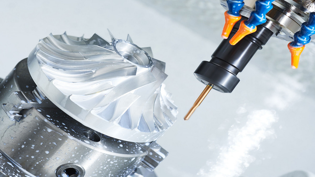
Chip formation is part of the process of mechanically removing material using tools such as saws, lathes, and milling cutters. Especially when cutting metal with the new high-speed steel tools, which are faster and more powerful.
Chip formation during machining:
Proper chip formation and evacuation ensure that the cutting process proceeds undisturbed, maintains operator safety, and does not damage the machine tool and workpiece. During machining, the removed material is plastically deformed and sheared in the shear plane and exits as long or short chips depending on the workpiece material. Processing consumes most of its energy in this shear zone. When processing incompressible materials, the material deforms in the shear plane without volume change. The deformation is assumed to occur as simple shear, and a stack of layers of material is placed in the material to be chipped. Each layer is parallel to the shear plane. Chip formation can be exemplified by a shearing process of a material layer.
What Chip Classifications are There?
The type of chip formed depends on many factors, including tool and material. The major factors are the angle formed by the tool facets and the angle between that angle and the surface. The sharpness of a cutting tool generally does not define the type of chip, but rather a clear distinction between the quality and type of chips. Dull tools produce degraded chips that are large, tear, and vary from one form to another, often leaving a poor-quality finish that signifies variation.
- Type I chip:
Type I chips form when the material splits before the cutting edge, perpendicular to the surface due to some upward wedging action of the tool exceeding the tensile strength of the material. As such, they are especially important in fibrous materials, where individual fibers are strong, but can be pried open relatively. Type I chips are formed when cutting tools with shallow cutting angles. Type I chips may form long, continuous chips whose size is limited only by the length of the cut. This is ideal chip formation for shavings, especially those produced by a well-adjusted flat surface with finely adjusted nozzles.
- Type II chip:
Type II chips are formed when the wedge shape of the cutter corners creates a shear force. Material fails along the short angle plane, starting at the apex of the tool edge, diagonally up and forward to the surface. The material deforms along this line, forming chips that curl upward. These chips are usually formed by intermediate cutting corners. Type II chips may form in ductile materials. Type II chips may form long, continuous chips.
- Type III chip:
Compressive failure of Type III chip-forming material, before a relatively obtuse cutting angle, approaches 90°. In some brittle or non-ductile materials, this may form acceptable swarf, usually fine dust. This chip consists of routers. It is formed by woodworking scrapers, although when properly sharpened and used they form a type III chip so thin that it looks like a well-formed type II chip. Their debris is thin enough and the compression failure volume is small enough to serve as a Type II well-defined shear plane.
The Basic Form of Chips:
- Discontinuous or Segmental Chips:
Indicates that the chip breaks into small pieces after it breaks away from the front of the tool. This is more likely to be the case with more brittle materials, such as cast iron or bronze. Because the chip is broken after it is formed, it will not exert pressure on the tool surface, and the remaining irregular surface can be easily cut flat by the blade, so a smoother surface can be obtained, and because the pressure on the tool surface is small, the wear it is small, so the tool life is longer. Non-continuous chipping of materials with a higher coefficient of friction or higher ductility is indicative of poor cutting conditions.
- Continuous Chips:
For materials with low ductility and low coefficient of friction, during cutting, the metal continuously deforms and flows on the tool surface, and acts stably on the tool. Therefore, no matter in terms of surface finish or tool life, it is a reasonable chip, and it is convenient for the analysis of cutting force.
- Continuous Chip with Built-Up-Edge:
BUE For materials with high flexibility and high friction coefficient, during the cutting process, due to the pressure between the very high friction coefficient and chips, there are some particles bonded on the tool surface. When the cutting continues, the bonding The more material there is, the more it accumulates to an appropriate height, it will be lost with the chips, or part of it will be embedded in the working surface. Since this effect occurs periodically, the smoothness of the machined surface is much lower than that of the continuous chip. This phenomenon can be reduced by reducing the chip thickness and increasing the inclination angle.
Chip Formation is Applied in the ISO System:
- ISO group P (steels) includes materials with fairly high ductility and long chipping tendency. They require proper precautions to keep chips in an acceptable shape and length.
- ISO groups K (cast materials) and H (hard steels) include low-ductility materials that produce short chips. This simplifies chip control.
- ISO groups M (stainless steels), S (super alloys), and N (non-ferrous materials) include materials with relatively low ductility but significant adhesion. These materials form so-called build-up chips.

(4059)(20260924)(原).jpg)
(2367)(20260924)(原).jpg)