With the constant development of modern technology, the power output of equipment, such as internal combustion engines and motors is getting stronger and stronger. To attain the full efficiency of these power sources, reducers are incorporated.
What Is A Reducer?
A mechanical reducer is an independent closed transmission device between the prime power source and the working machine, used to reduce the speed and increase the torque to meet the needs of various machines.
For industrial manufacturing, the main function of the reducer is to decelerate a machines operation, that is, to reduce the speed of machinery. Reducing the speed in turn increase the torque. It is used along with electric motors, internal combustion engine, and other high-speed power sources. The input shaft, which has a gear with a small number of teeth on it, is meshed with a gear on the output shaft which has a larger number of teeth on. When the input shaft rotates at a high speed, the motion is transferred to the output shaft, which rotates at a slower speed.
The reducer has a wide range of industrial applications. The reducer is used for decelerating and increasing torque, so is widely used in speed and torque conversion equipment. For example, gear reducers can be seen in almost all types of mechanical transmission systems, from vehicles, ships, automobiles, locomotives, and heavy machinery used in construction. It is also used in the machinery industry, such as for processing machines and automated production equipment, as well as for common household appliances, clocks, and watches.
Overview of the Operation Principle of A Reducer
The reducer is a type of transmission. The principle is to engage the electric motor, internal combustion engine, or other high-speed power source through a gear mechanism to reduce the rotation speed of a machine device. The ratio of the number of teeth on the large gear with the number on the small gear is the reduction ratio (transmission ratio).
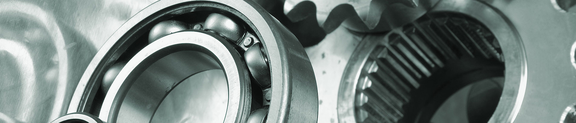
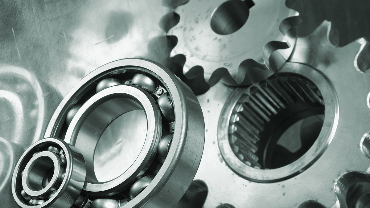
Reducer can be composed of any of a variety of gears such as worm gear, cycloid gears, planetary gears etc., and are usually enclosed in some type of rigid case. Gear shape can be divided into cylindrical gears, bevel gears, and conical-cylindrical gears. Transmission arrangement can be divided into expansion type, spur-flow, and co-entry shaft reducers. Reducers can also be divided into single-stage and multi-stage reducers according to the number of transmission stages.
The Difference between A Geared Motor and A Reducer
Reduction motors, also known as gear reduction motors and gear motors, are modular combinations. They combine a motor and a reducer.
Electric motors have varying speeds, which generally corresponds to the number of poles in the motor. For example, the output speed of a motor with 4 poles using 60 Hz power source will run at around 1800rpm, 6 poles at around 1200rpm, 8 poles at around 900rpm. Motors with a higher number of poles are more expensive, run slower and have higher torque. As common motors generally use 4 poles, instead of buying a more expensive motor with more poles, the 4-pole motor can be used along with a reducer to get the same speed and torque of a motor with more poles. The reducers used for this purpose are generally relatively small.
The Benefits of Using Reducers
If a high torque is needed for some type of work, you may need to increase the size of the motor, or use a motor that uses a higher current. This will increase the overall cost of the system. The size of the motor will also be larger, increasing the space requirement for the equipment. But if a reducer is used, the torque can be increased without the need to invest in a larger motor and with only a small increase in the size of the system.
Common Types of Reducers
- Single-stage cylindrical gear reducer:
A single-stage cylindrical gear reducer is suitable for a reduction ratio of 3~5:1. The gear teeth can be straight, helical, or herringbone shape. The gear box is usually made of cast iron or welded steel plates. Roller bearings are commonly used, and sliding bearings are only used for heavy loads or extremely high speeds.
- Two-stage cylindrical gear reducer:
Two-stage cylindrical gear reducers are divided into three types: expansion type cylindrical gear reducer, split type cylindrical gear reducer, and coaxial type cylindrical gear reducer, and are suitable for reduction ratios of 8-40.
- Expansion style: High-speed or low speed helical gears with long shafts. Because the torque input and output ends are far away from the gear meshing area, and due to the asymmetrical arrangement of the gear relative to the bearing, there is uneven distribution of load along the tooth width caused by the bending and deformation of the shaft. To reduce the uneven distribution on the gears, high rigidity is required for the shaft. A simple structure is most widely used.
- Spur type: Generally used for high-speed applications. Because the gears are arranged symmetrically, they can be used where the force on the gear and the bearing will be large. To make the total axial force on the shaft smaller, the helix directions of the two pairs of gears should be opposite. This structure is more complicated, and it is often used in places with high power and variable loads.
- Coaxial type: The axial size of the reducer is larger, the intermediate shaft is longer, and the rigidity is poor. When the oil immersion depths of the two large gears are similar, the load-carrying capacity of the high-speed gears cannot be fully utilized. These gears are often used in places where the input and output shafts are coaxial.
- Single-stage bevel gear reducer:
A single-stage bevel gear reducer is suitable for a reduction ratio of 2~4:1. The transmission ratio should not be too large to keep the size of the bevel gear required low, and to facilitate load transfer. Bevel gear reducers are used in transmissions where two axes intersect perpendicularly.
- Conical and cylindrical gear reducer:
Conical and cylindrical gear reducers are suitable for reduction ratios of 8-15:1. These gears work best for high-speed applications where small size bevel gears are used. Bevel gears can have straight or curved teeth. Cylindrical gears are usually made with helical teeth, which can offset part of the axial force of bevel gears.
- Worm gear reducer:
There are mainly cylindrical worm gear reducers, arc toroidal worm gear reducers, conical worm gear reducers, and worm gear reducers, among which cylindrical worm gear reducers are the most used.
- Worm gear reducer is suitable for a reduction ratio of 10~80. The structure is compact, the transmission ratio is large, but the transmission efficiency is low, and it is suitable for the occasions of small power and gap work. When the peripheral speed of the worm is V≤4~5m/s, the worm is under-mounted, and the lubrication and cooling conditions are better; when V≥4~5m/s, the agitation loss of the oil is larger, and the worm is generally the upper-mounted type.
- Planetary gear reducer:
Due to the structure of the planetary gear reducer (planetary reducers), the minimum single-stage reduction is 3, and the maximum generally does not exceed 10. The common reduction ratio is 3/4/5/6/8/10, and the number of stages of the reducer generally does not exceed 3, but some are large. The reduction ratio custom reducer has 4 levels of reduction.
Compared with other reducers, planetary gear reducer has high rigidity, high precision (single-stage can be within 1 minute), high transmission efficiency (single-stage 97%-98%), high torque, volume ratio, lifetime maintenance-free, etc. features. Because of these characteristics, planetary reducers are mostly installed on stepper motors and servo motors to reduce speed, increase torque, and match inertia.