The turning process is to make the material reach the desired shape by removing the material, and its machining accuracy is high and there is no mold restriction. But the production cost is high and the processing speed is slow.
What is the Turning Process?
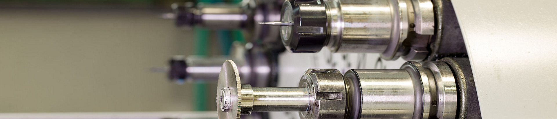
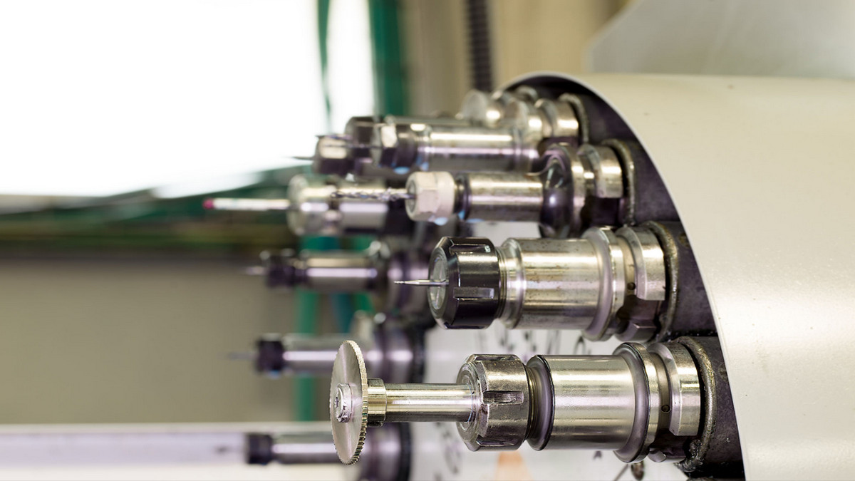
Turning means that lathe processing is a part of mechanical processing. Lathe machining mainly uses turning tools to turn the rotating workpiece. Lathes are mainly used for machining shafts, discs, sleeves, and other workpieces with revolving surfaces, and are the most widely used machine tools in machine manufacturing and repair factories.
Use the rotary motion of the workpiece and the linear or curvilinear motion of the tool to change the shape and size of the blank, and process it to meet the requirements of the drawing. The cutting energy of turning is mainly provided by the workpiece rather than the tool. Turning is the most basic and common cutting method and plays a very important role in production. Turning is suitable for machining rotary surfaces. Most workpieces with rotary surfaces can be processed by turning methods, such as inner and outer cylindrical surfaces, inner and outer conical surfaces, end faces, grooves, threads, and rotary forming surfaces. The tools used are turning tools.
A workpiece is usually machined on a lathe for two reasons: to cut it to size and to produce a true diameter. Workpieces that must be cut to size and have the same diameter along their entire length involve parallel turning operations. Many factors determine the amount of material that can be removed on a lathe. The diameter should be cut to size in two cuts: roughing and finishing. To have the same diameter at each end of the workpiece, the center of the lathe must be in line.
To set the exact depth of cut:
- Set the compound rest to 30 degrees.
- Attach the roughing or finishing tool. If feeding the saddle toward the headstock, use a right-hand turning tool.
- Move the knife holder to the left side of the compound support and set the knife head to the right height center.
- Set the lathe to the correct speed and feed for the diameter and type of material being cut.
- Start the lathe and lightly cut about 0.005" and 0.250" long on the right-hand end of the workpiece.
- Stop the lathe, but do not move the infeed screw handle.
- Turn the carriage handwheel to move the tool to the end (right side) of the workpiece.
- Measure the workpiece and calculate the amount of material to be removed.
- Turn the scale ring by half the amount of material to be removed. For example, if 0.060 inches is to be removed, the scale ring should be turned in by 0.030 inches because the notch is removed from the circumference of the workpiece.
- For every thousandth of the cutting depth, the diameter of the blank is reduced by two thousandths.
What is a Rough Turning?
Rough turning operations are used to remove as much metal as possible in the shortest amount of time. In this operation, precision and surface finish is not important. Therefore, a maximum depth of 0.030 inches and a feed of 0.020 to 0.030 inches are recommended. The workpiece is typically roughed to within about 0.030" of the finished size in as many cuts as possible.
- Set the lathe to the correct speed and feed rate for the type and size of material being cut.
- Adjust the quick-change gearbox to a feed of 0.010 to 0.030 inches depending on the depth of cut and machine condition.
- Move the knife holder to the left of the compound holder and set the knife head to the correct height to center.
- Tighten the tool holder to prevent the tool holder from moving during machining.
- Make a light trial cut approximately 0.250" long on the right-hand end of the workpiece.
- Measure the workpiece and adjust the tip for the proper depth of cut.
- Cut about 0.250", stop the lathe and check the diameter for size. The diameter should be approximately 0.030" above the finish.
- If necessary, readjust the depth of the cut.
What is Complete Turning?
Turning is done on a lathe and, after rough turning, produces a smooth surface finish and cuts the workpiece to precise dimensions. Factors such as the condition of the cutting tip, the rigidity of the machine and workpiece, and the speed and feed rate of the lathe can all affect the type of surface finish produced.
- Check that the cutting edge of the cutter head is free of nicks, burns, etc. It is a good idea to home the cutting edge before making a fine cut.
- Set the lathe to the recommended speed and feed rate. The feed rate used depends on the desired surface finish.
- Make a light trial cut about 0.250" long on the right-hand end of the workpiece to produce the true diameter, set the cutting tool bit to the diameter and the scale ring to the correct diameter.
- Stop the lathe and measure the diameter.
- Set the depth of cut to half the amount of material to be removed.
- Cut 0.250", stop the lathe, and check the diameter.
- If necessary, readjust the depth of the cut and complete the turning diameter. To produce the truest diameter possible, the workpiece is finished to the desired size. If coating or polishing is required to complete the diameter, do not leave more than 0.002 to 0.003 inches of space in this operation.
What is a Shoulder Turning?
When turning multiple diameters on a workpiece. The change in diameter or step is called a shoulder. Three common shoulder types: square, rounded and tapered.
- Mount the workpiece on the lathe and position the shoulders from the finished end of the workpiece. In the case of a rounded shoulder, all-sufficient lengths allow the proper radius to be formed on the finished shoulder.
- Place the tip of the cutter head at this mark and cut a small groove around the circumference to mark the length.
- Using the turning head, rough and finish the workpiece approximately 0.063 inches to the desired length.
- Set up the end face tool. Chalk the small diameter of the workpiece, then lift the cutting tool until it just removes the chalk marks.
- Note the reading on the infeed handle scale ring.
- At right angles to the shoulder, use the hand feed to cut to the line.
- For continuous cuts, return the cross-feed handle to the same scale ring setting.
If a fillet is required, use a tip with the same radius to finish the shoulder. An angled or chamfered edge can be obtained by setting the cutting edge of the cutter head to the desired chamfer angle and feeding it against the shoulder, or by setting the compound tool holder to the desired angle.
Things to Consider when Turning:
- Reasonable selection of cutting amount:
For high-efficiency metal cutting, the material to be processed, the cutting tool, and the cutting conditions are the three major elements. These determine machining time, tool life, and machining quality. An economical and effective machining method must be a reasonable choice of cutting conditions. The three elements of cutting conditions: cutting speed, feed, and depth of cut directly cause tool damage. With the increase in cutting speed, the temperature of the tooltip will rise, which will cause mechanical, chemical, and thermal wear. A 20% increase in cutting speed reduces tool life by 1/2. The relationship between the feed conditions and the wear behind the tool occurs within a very small range. But the feed rate is large, the cutting temperature rises, and the back wear is large. It has less effect on the tool than cutting speed. Although the effect of the depth of cut on the tool is not as large as the cutting speed and feed, when cutting with a small depth of cut, the material to be cut will produce a hardened layer, which will also affect the life of the tool. The user should select the cutting speed to be used according to the material to be processed, hardness, cutting state, material type, feed rate, depth of cut, etc. The selection of the most suitable processing conditions is based on these factors. Regular, steady wear to life is the ideal condition. However, in practice, the choice of tool life is related to tool wear, dimensional changes to be machined, surface quality, cutting noise, machining heat, etc. When determining the processing conditions, it is necessary to study according to the actual situation. For difficult-to-machine materials such as stainless steel and heat-resistant alloys, coolants or rigid cutting edges can be used.
- Reasonable choice of tools:
- When rough turning, a tool with high strength and good durability should be selected, to meet the requirements of a large amount of knife and large feed during rough turning.
- When finishing turning, tools with high precision and good durability should be selected to ensure the requirements of machining accuracy.
- To reduce tool change time and facilitate tool setting, machine-clamped knives and machine-clamped blades should be used as much as possible.
- Reasonable selection of fixtures:
- Try to use general fixtures to clamp the workpiece, and avoid using special fixtures.
- The positioning datum of the parts is coincident to reduce the positioning error.
- Determine the processing route:
The machining route is the movement track and direction of the tool relative to the part during the machining process of the index-controlled machine tool.
- It should be able to ensure the machining accuracy and surface roughness requirements.
- The processing route should be shortened as much as possible to reduce the idle travel time of the tool.
- The connection between machining route and machining allowance:
At present, under the condition that the numerical control lathe has not yet reached popular use, it is generally necessary to arrange the excessive allowance on the blank, especially the allowance containing the forged and cast hard skin layers, to be processed on the ordinary lathe. If it must be processed with a CNC lathe, it is necessary to pay attention to the flexible arrangement of the program.
- Fixture installation points:
At present, the connection between the hydraulic chuck and the hydraulic clamping cylinder is realized by a pull rod. The main points of the hydraulic chuck clamping are as follows: first, remove the nut on the hydraulic cylinder with a wrench, remove the pull tube, and pull it out from the rear end of the main shaft, and then the chuck can be removed by removing the chuck fixing screws with a wrench.