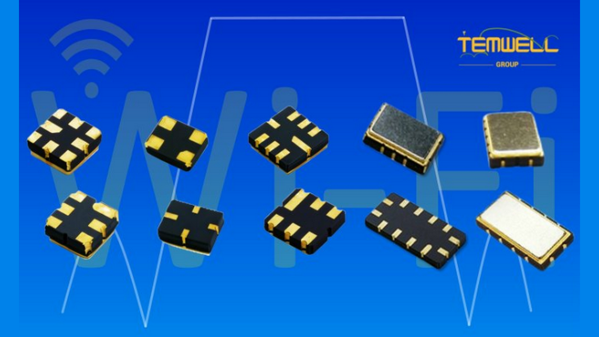
Wi-Fi 6E and Wi-Fi 7 Raise the Bar for RF Filter Design
Wi-Fi is entering a new RF design phase. Wi-Fi 6E extends Wi-Fi 6 into the 6 GHz spectrum, while Wi-Fi 7 builds on that expansion with features such as 320 MHz channels, Multi-Link Operation (MLO), and 4K QAM. These capabilities can improve throughput, responsiveness, and reliability, but they also raise the performance bar for every RF signal path.
For product teams, the implication is straightforward: a wireless chipset alone cannot guarantee a strong user experience. The antenna, PCB layout, shielding, power design, and RF Filter strategy must work together. A filter that was adequate for an earlier 2.4 GHz and 5 GHz design may not provide enough bandwidth, rejection, or thermal stability for a Wi-Fi 6E or Wi-Fi 7 product.
This matters to more than access point manufacturers. Industrial gateways, enterprise routers, mesh systems, smart cameras, medical devices, connected vehicles, test equipment, and AIoT platforms increasingly need to operate in crowded RF environments. Buyers must therefore evaluate RF components not only by unit price, but also by their effect on certification risk, system margin, production consistency, and long-term upgradeability.
Why the 6 GHz Band Changes the RF Filter Conversation
The 6 GHz band gives Wi-Fi access to substantial new spectrum, although the exact available range depends on local regulation. In the United States, the FCC opened 1,200 MHz from 5.925 GHz to 7.125 GHz for unlicensed use, while many other markets have adopted only the lower 6 GHz range, typically 5.925 GHz or 5.945 GHz to 6.425 GHz. This regional difference is important for product planning because one global hardware platform may require different operating profiles, filter specifications, or certification plans.
Wi-Fi 6E uses this new spectrum to reduce pressure on heavily used 2.4 GHz and 5 GHz bands. Wi-Fi 7 goes further. The Wi-Fi Alliance states that Wi-Fi 7 supports 320 MHz channels in the 6 GHz band, which can provide twice the channel width of Wi-Fi 6. It also supports Multi-Link Operation, allowing traffic to use more than one band or channel link for higher reliability and lower latency.
However, wider available spectrum does not remove interference concerns. It changes them.
A 6 GHz-capable device may operate beside:
- Other Wi-Fi access points and client devices
- Legacy 2.4 GHz and 5 GHz radios in the same product
- Bluetooth radios and cellular modules
- GNSS, private radio, radar, or microwave equipment, depending on the application
- Existing licensed services that regulators seek to protect
- Internal noise sources from processors, memory, switch-mode power supplies, displays, and high-speed interfaces
An RF Filter acts as a frequency gate. It passes the signals the radio needs and attenuates signals that could degrade receiver sensitivity, overload active components, or create unwanted emissions. In a wide-channel Wi-Fi 7 design, this gate must be wide enough to preserve the wanted signal while becoming selective quickly outside the operating range.
That is the core engineering challenge: wide passband performance and strong out-of-band rejection must coexist.
Wide Channels Create a Tougher Selectivity Trade-Off
A common misconception is that Wi-Fi 7 always needs the widest possible RF Filter. In reality, the appropriate passband depends on the channel plan, target markets, radio architecture, and coexistence conditions.
For example, a product designed to use a full 320 MHz Wi-Fi 7 channel needs a passband that supports the intended channel without excessive attenuation or distortion. Yet an unnecessarily broad filter may allow more unwanted energy into the receiver. This can reduce blocking performance and leave less protection against nearby radios or internal spurious signals.
The table below shows how Wi-Fi generations change the practical RF filtering task.
| Wireless generation |
Relevant band capability |
Main RF filter concern |
Procurement implication |
| Wi-Fi 5 |
2.4 GHz and 5 GHz, up to 160 MHz channels |
Legacy coexistence and moderate bandwidth |
Standard dual-band filtering may be sufficient for many designs |
| Wi-Fi 6 |
2.4 GHz and 5 GHz, up to 160 MHz channels |
Dense-device efficiency and receiver protection |
Verify loss, rejection, and lot-to-lot consistency |
| Wi-Fi 6E |
Adds 6 GHz operation |
Separation of 6 GHz from existing 5 GHz paths and regional band planning |
Confirm the exact regulatory frequency range before sourcing |
| Wi-Fi 7 |
2.4 GHz, 5 GHz, and 6 GHz; up to 320 MHz in 6 GHz |
Wide passband, low loss, sharp rejection, multi-link coexistence |
Request full S-parameters and system-level validation support |
The difficult area is often the filter transition between passband and stopband. This is described as the filter skirt. A steep skirt allows a component to preserve a wide wanted band while suppressing unwanted frequencies just outside it. In Wi-Fi 6E and Wi-Fi 7 systems, steep skirt attenuation can be especially valuable where the radio front end must reject nearby transmitters, protect a low-noise amplifier, or meet emissions limits with limited PCB space.
Still, steep rejection is not automatically the best answer. A highly selective component may introduce more insertion loss, larger physical dimensions, higher cost, or tighter tuning sensitivity. The correct decision is based on the system budget, not one isolated specification.
The RF Filter Specifications Buyers Should Ask For
Procurement teams often receive a short request: “Need a 6 GHz Wi-Fi filter.” That description is not enough to compare suppliers or protect a product schedule. A useful RF Filter specification should define the radio environment and the intended performance clearly.
Before requesting quotations, engineering and sourcing teams should agree on the following items.
1. Operating Frequency and Passband
State the lowest and highest frequencies the filter must pass, not only the center frequency. For a wideband Wi-Fi application, specify whether the component must support the lower 6 GHz band, the full 5.925 GHz to 7.125 GHz range where permitted, or a narrower planned channel block.
A filter selected for a narrow 6 GHz allocation may not be suitable for markets that permit the full 6 GHz band. Conversely, specifying the full range when the product will only use a smaller block can increase cost or reduce rejection margin without creating customer value.
2. Insertion Loss
Insertion loss is the amount of wanted signal power lost as it passes through the filter. It directly affects transmitter efficiency and receiver sensitivity.
In a receive path, every dB of loss ahead of the low-noise amplifier consumes part of the link budget. In a transmit path, loss reduces radiated output or increases the burden on the power amplifier. This makes low insertion loss important, especially in battery-powered products, long-range industrial deployments, and high-throughput access points.
Do not evaluate the “typical” insertion-loss value alone. Ask for:
- Maximum insertion loss across the full operating band
- Insertion loss at temperature extremes
- Variation between production lots
- Test conditions and reference impedance
- Data at the intended PCB mounting configuration
3. Return Loss and VSWR
Poor impedance matching reflects energy back toward the source instead of transferring it efficiently. Return loss and VSWR indicate how well the RF Filter is matched to the system, typically 50 ohms.
A component can show acceptable insertion loss but still create unwanted reflections when integrated with an antenna, RF switch, amplifier, or transmission line. For this reason, supplier data should be reviewed alongside the complete RF chain rather than in isolation.
4. Stopband Rejection and Skirt Attenuation
Stopband attenuation defines how much an unwanted signal is reduced. Buyers should identify specific frequencies that matter, such as the neighboring Wi-Fi band, a cellular harmonic, a local oscillator leakage product, or a known internal noise source.
A vague request for “high attenuation” invites vague supplier responses. A better requirement is: “Provide at least the required attenuation at the identified interference frequencies under the defined temperature range.” This turns a marketing term into a measurable sourcing requirement.
5. Group Delay and Group-Delay Variation
Wi-Fi uses wide, high-order modulation schemes. Wi-Fi 7 can use 4096-QAM, also called 4K QAM, which increases the amount of information carried in a radio signal. These higher-order modulations generally leave less room for signal distortion.
Group delay is the time different frequency components take to pass through a filter. Large variation across the passband can distort a wideband signal. Not every application needs an unusually tight group-delay requirement, but it should be reviewed when designing high-capacity links, test systems, or products targeting demanding Wi-Fi 7 performance.
6. Power Handling, Size, and Environmental Stability
A compact client device and a high-power enterprise access point do not need the same RF Filter technology. Confirm continuous-wave and peak power handling where applicable, as well as the connector or surface-mount package, mounting method, operating temperature, vibration expectations, humidity requirements, and compliance needs.
These criteria prevent a common problem: selecting a part that performs well in a bench measurement but shifts or degrades after real-world thermal and mechanical stress.
Which RF Filter Technology Fits Wi-Fi 6E and Wi-Fi 7?
There is no universal “best Wi-Fi 7 filter.” Technology selection is a balancing exercise among frequency range, bandwidth, rejection, power level, footprint, tuning needs, and target cost.
The following comparison offers a practical starting point.
| RF filter approach |
Typical strengths |
Typical trade-offs |
Suitable Wi-Fi-related use cases |
| SAW filter |
Compact size, repeatable response, suitable for high-volume RF modules |
Power handling and frequency options depend on design; performance must be checked at 6 GHz |
Compact client devices, radio modules, selected front-end paths |
| Ceramic or dielectric resonator SMD filter |
Compact, good RF performance, useful balance of size and selectivity |
May have narrower design trade-offs than a cavity solution |
Embedded devices, industrial gateways, compact infrastructure |
| Helical filter |
Tunable designs, good selectivity in suitable bands |
Size and high-frequency applicability must be reviewed carefully |
Specialized radio paths and legacy or custom band requirements |
| Cavity filter |
High Q, strong selectivity, high-power capability, robust performance |
Larger and often heavier than SMD alternatives |
Enterprise infrastructure, base stations, test systems, high-power or demanding interference environments |
| Diplexer, multiplexer, or combined filter network |
Helps separate or combine multiple paths in one RF architecture |
Requires system-level design to control interaction among paths |
Tri-band Wi-Fi, Wi-Fi plus cellular, distributed antenna and multi-radio equipment |
The best technology is therefore the one that solves the real interference and integration problem with enough manufacturing margin. It is not necessarily the smallest, lowest-cost, or highest-rejection part when viewed alone.
Wi-Fi 7 Makes System-Level Coexistence Essential
Wi-Fi 7’s Multi-Link Operation is designed to improve throughput, reliability, and latency by using multiple links. This creates a valuable system capability, but it also makes RF coexistence more important inside the product.
Consider a tri-band access point that can transmit and receive through 2.4 GHz, 5 GHz, and 6 GHz radios. Strong in-device transmissions can desensitize a nearby receiver if isolation, filtering, antenna placement, and control logic are inadequate. The problem can become more visible under simultaneous traffic, high output power, temperature change, or an unfavorable antenna orientation.
An RF Filter cannot solve every coexistence issue. It must be paired with:
- Careful antenna-to-antenna isolation
- Appropriate RF switching and diplexing architecture
- Low-noise power regulation
- Shielding between high-speed digital and RF sections
- Controlled impedance PCB routing
- Proper grounding and via fences
- Validation under simultaneous transmit-and-receive conditions
For buyers, this means a component quotation should not end the technical discussion. A capable supplier should be able to discuss the intended architecture, identify missing parameters, and provide data that engineers can use in simulation and prototype evaluation.
A Practical RF Filter Sourcing Workflow
The lowest-risk approach is to involve an RF filter supplier before the PCB layout is frozen. Late-stage filter changes can force antenna retuning, layout revisions, enclosure changes, new EMC testing, and costly schedule delays.
A disciplined sourcing workflow includes five steps.
Step 1: Define the Market and Channel Plan
List every country or region in which the product will be sold. Confirm the permitted 6 GHz range, power class, and applicable regulatory requirements for each market. The global 6 GHz landscape remains uneven, so a single “worldwide 6 GHz” assumption may create unnecessary exposure.
Step 2: Map the Full RF Environment
Document all intentional radios, harmonics, clocks, switching regulators, cables, and external RF sources. Identify the signals most likely to create receiver blocking or unwanted emissions.
Step 3: Set Measurable Filter Requirements
Define passband, maximum insertion loss, minimum attenuation at critical frequencies, return loss, group delay if applicable, power, size, operating temperature, and mechanical needs. Include target and minimum acceptable values separately.
Step 4: Review S-Parameters and Prototype Data
Ask for S-parameter files, not only a catalog plot. Engineers can use these files to model the filter with the amplifier, switch, antenna, and PCB network. Then verify performance on an assembled prototype across frequency, temperature, and operating modes.
Step 5: Qualify Supply and Production Control
For production programs, review quality systems, material controls, inspection methods, lead time, change notification practices, and capacity planning. RF performance consistency is as important as a strong first sample.
Supplier Questions That Reduce Project Risk
Before awarding a Wi-Fi 6E or Wi-Fi 7 RF Filter program, buyers can use this checklist:
- Can the supplier support the exact 6 GHz frequency range required in each target market?
- Is the stated insertion loss typical or guaranteed across frequency and temperature?
- At which specific frequencies is stopband attenuation guaranteed?
- Can the supplier provide S-parameters, test reports, and production limits?
- Has the filter been evaluated with the intended RF power and duty cycle?
- What is the expected performance shift after reflow, vibration, humidity, or thermal cycling?
- Can the mechanical size, connector, impedance, or attenuation profile be customized?
- What engineering support is available if the first PCB revision does not meet coexistence targets?
- How are component changes communicated after qualification?
- Can supply continuity be supported for the planned product life cycle?
These questions shift sourcing from buying a component to managing RF performance risk.
FAQ: Wi-Fi 6E and Wi-Fi 7 RF Filters
Does Wi-Fi 7 require a completely new RF Filter?
Not always. The requirement depends on the supported frequency bands, channel widths, power levels, and product architecture. A Wi-Fi 7 product using 6 GHz and 320 MHz channels may need a wider and more carefully controlled filter response than a Wi-Fi 6 product, but the correct solution should be determined from the complete RF design.
Why is low insertion loss so important in a 6 GHz design?
At higher frequencies, link budget can become more sensitive to losses in filters, PCB traces, switches, and connectors. Lower insertion loss helps preserve receiver sensitivity and transmitter efficiency. The value must still be balanced against rejection, size, and cost.
Can software solve 6 GHz coexistence problems?
Software can manage channel selection, power, scheduling, and Multi-Link Operation. It cannot remove unwanted RF energy entering a receiver, poor antenna isolation, or inadequate emissions suppression. Hardware filtering remains a core part of coexistence design.
Should a global Wi-Fi product use one 6 GHz filter specification?
Possibly, but not by default. Countries do not all authorize the same 6 GHz range. Product teams should first identify target markets, then decide whether one wideband design or multiple regional variants offers the better balance of performance, cost, and certification complexity.
What should be tested after selecting an RF Filter?
Test the assembled product, not the filter alone. Key checks include insertion loss, return loss, receiver sensitivity, blocking, spurious emissions, adjacent-channel behavior, thermal performance, and simultaneous operation of all installed radios.
Making the 6 GHz Opportunity More Reliable
Wi-Fi 6E and Wi-Fi 7 create meaningful opportunities for faster and more responsive wireless products. The 6 GHz band, 320 MHz channels, and multi-link designs also make RF margins more valuable. A well-specified RF Filter helps protect those margins by preserving wanted signals and suppressing interference before it limits real-world performance.
For buyers, the most effective decision is to specify the operating environment clearly, ask for measurable performance data, and validate the component in the full radio system. This approach reduces late redesigns and gives a product a stronger foundation for evolving wireless standards.
Temwell Corporation is a Taiwan-based provider of custom RF filters and microwave components. Its published portfolio includes cavity filters, SMD ceramic filters, SAW filters, helical bandpass filters, diplexers, multiplexers, and related RF components. For teams assessing a custom solution for wideband Wi-Fi, multi-radio, or 6 GHz coexistence requirements, its portfolio is a relevant starting point for technical discussion. Discuss RF Filter Solutions with Temwell