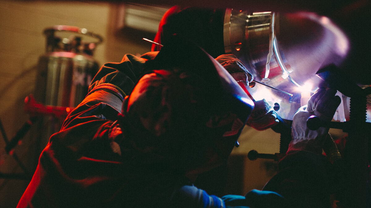
The main advantages of the SAW process are high quality and high productivity. The process can be implemented in three different operating modes-semi-automated, mechanized and automated.
The submerged arc welding process
Welding specification and its influence
The main welding specifications for submerged arc welding are welding current, welding voltage, and welding speed, followed by the wire diameter, wire extension length, flux and wire type, flux particle size and flux layer thickness. All these specifications have varying degrees of influence on weld formation and welding quality. In addition, the inclination of the weldment under the same welding specification also directly affects the weld formation.
-
Welding current
The welding current directly determines the welding wire melting speed, penetration depth and the amount of base metal melting. Increasing the welding current can accelerate the welding wire melting speed and improve welding productivity. At the same time, the arc blowing force increases with the welding current, the metal in the molten pool is discharged by the arc, so that the unmelted base metal at the bottom of the molten pool is directly heated by the arc, and the penetration depth increases. Excessive current will cause the steel plate to burn through. Excessive current will also cause the weld seam to be too high, the heat-affected zone will increase and cause large welding deformation. The current decreases and the penetration depth decreases. If the current is too small, it is easy to cause under-welding and the arc stability is not good. The current change has little effect on the melt width change.
-
Welding voltage
The welding voltage is the voltage between the end of the welding wire and the surface of the molten metal, that is, the voltage across the arc. Because this voltage is difficult to measure, the actual production is to measure the voltage between the contact tip and the workpiece, which can be read by the voltmeter on the machine head. When the welding cable is long, due to the large current, there is a voltage drop on the cable. The indicated value of the voltmeter on the welding power supply is higher than the indicated value of the voltmeter on the machine head by more than 1 ~ 2 volts. When adjusting the welding voltage, it should be carried out according to the indicated value of the voltmeter on the machine head.
The welding voltage has little effect on the melting speed of the welding wire but has a great influence on the weld cross-section and appearance. As the welding voltage increases, the arc length increases, the arc's range of motion increases, and the melt width increases. At the same time, the weld height and penetration depth decrease slightly, and the weld becomes flat. After the arc active range is increased, the flux melting amount is increased, and if it is an alloy-containing sintered flux, the alloy element transitioning to the weld increases. When the assembly gap is slightly larger, the increased voltage is beneficial to weld formation.
When the welding voltage is too high, a "mushroom" weld will be formed during butt welding, which is prone to cracks in the weld; fillet welding will cause undercut and dent welds. If the welding voltage continues to increase, the arc will break through the coverage of the slag, leaving the molten metal unprotected and in contact with the air, causing dense pores. When the welding voltage is reduced, the melting width is reduced, and the weld becomes high and narrow. If the welding voltage is too low, it will cause insufficient melting of the base material, poor weld formation and difficulty in slag removal.
-
Welding speed
The welding speed has a significant effect on the melting width and depth. Under the conditions of other specifications unchanged, when the welding speed increases, the heating of the arc to the base material decreases and the melting width decreases significantly. At the same time, the effect of the arc repelling the molten pool metal to the rear is strengthened, and the arc directly heats the base material in the lower part of the molten pool, so that the melting depth is slightly increased. When the welding speed is increased to more than 40 meters/hour, the penetration of the base metal is significantly reduced by the arc, and the penetration depth decreases as the welding speed increases. Excessive welding speed will cause defects such as undercut, under-welding, and rough weld seam. When the welding speed is reduced, the volume of the molten pool increases and the existence time increases, which is beneficial to the gas floating out of the molten pool and reduces the tendency to form pores. However, if the welding speed is too low, a fragile "mushroom-shaped" weld may be formed, or defects such as burn-through, slag inclusions, and irregular welds may occur. For fillet welds, increasing the welding speed can increase productivity. For butt welds with grooves, changes in welding speed have little effect on productivity.
-
The diameter of the welding wire
The wire diameter mainly affects penetration. Under the same welding current, the welding wire current density of different diameters is different, the welding wire current density of the thinner diameter is larger, and the blowing force of the arc is large and the penetration depth is large. When the welding wire is thin, the current density is large, and it is easy to start the arc.
The thicker the wire, the greater the current allowed and the higher the productivity. When the assembly is poor, the operation performance of the thick welding wire is better than that of the thin welding wire, which is conducive to controlling the formation of the welding seam and is not easy to burn through. The diameter of the welding wire should be adapted to the size of the welding current used. If the thick wire is welded with a small current, the welding arc will be unstable; on the contrary, the thin wire will be welded with a large current, which is easy to form a "mushroom" weld and the molten pool is unstable, Poor weld formation. Suitable welding current range for different diameter welding wire.
-
Extension length
The welding wire extension length refers to the length of the welding wire extending out of the contact tip, which is the distance from the lower end of the contact tip to the surface of the molten pool. For the convenience of measurement, the distance from the lower end of the contact tip to the surface of the weldment is generally taken as the extension length. There is a certain resistance in the welding wire protruding out of the contact tip. The welding current of submerged arc welding is very large. The resistance heat generated in this part of the welding wire is very large. The preheating of the resistance heat received by the welding wire increases the melting speed and the diameter of the welding wire becomes thinner. Or the longer the extension length, the greater the preheating effect. Therefore, when the diameter of the welding wire is less than 3mm, the extension length must be strictly controlled; when the diameter of the welding wire is thicker, the influence of the extension length is smaller, but it should also be controlled within an appropriate range. The extension length should generally be 6 to 10 times the diameter of the welding wire. For materials with high resistance such as stainless steel welding wire, the extension length should be smaller to avoid overheating of the welding wire. If the extension length is too short, the arc will easily burn back to the contact tip. If the contact tip is made of copper, the weld will melt into copper and cause cracks, so the extension length should not be too short.
Submerged arc welding quality problems
Although this process usually produces high-quality weldments, there may be some quality problems and their reasons. The main advantages of using the submerged arc welding (SAW) process are high quality and high productivity. The process can be implemented in three different operating modes-semi-automated, mechanized and automated.
The main disadvantage of submerged arc welding is that plate and tube welding can only be performed in the flat or horizontal welding position (test position 1G or 2G).
Welding quality
Because the molten slag coating has excellent protection for the weld metal, SAW can produce high-quality welds with fewer welding defects than other processes. However, as with other processes that have many variable combinations, problems such as porosity, slag inclusion, incomplete fusion, and cracking also occur in SAW. The following are some of these problems and remedies.
Porosity
The weld metal deposited by SAW is usually clean and free of harmful pores, but when pores do occur, it may be found on the surface of the weld bead or a sound surface. Possible causes of porosity include:
Contaminants in joints, such as paint residues, hydrocarbons in oil-based products or manufacturing paints;Electrode contamination, such as rust oil due to improper storage; insufficient flux coverage; contaminants in the flux, especially contaminants in the recovered flux, may be reused if not properly screened; clips at the bottom of the weld Slag; segregation of the weld metal components; incorrect welding parameters, such as high voltage and excessive travel speed, will lead to rapid solidification and prevent gas from escaping; residues of the welding slag have been oxidized (residual) Objects may also form gas, inhibit melting and create voids); moisture in the flux will simultaneously produce hydrogen and oxygen cavitation; high flux burden; and arc strike.
As with other welding processes, base metals and electrodes must be cleaned and dried in SAW. The high travel speed and associated rapid weld metal solidification do not provide time for the gas to escape from the molten weld metal. Travel speed can be reduced, but other solutions should be studied first to avoid higher welding costs. Porosity caused by the covered electrode tack weld can be avoided by using a welding rod that does not leave any residues that cause porosity. The recommended spot welding electrodes are E6010, E6011, E7015, E7016 and E7018.
Inclusions
Inclusions in the weld are defined as entrapment of solid foreign objects such as slag, flux or oxide. As with all flux protection processes, if SAW is not applied correctly, it is not immune to slag inclusions. Inclusions are mainly found at the intersection of roots or between previous passes, usually located near the slope or groove surface. In the following cases, the risk of inclusions is greater:
In the downhill direction, this may cause the molten flux to run in front of the weld, and then roll off and sink into it during solidification; grooves along the edge of the previously deposited beads, especially if they are convex; the edge of the weld Whether there is undercut; when the arc instability inhibits the slag from rising to the top of the solidified weld; when using flux with too high viscosity, it will hinder the solidification of the weld; when the previous bead surface is not kept clean; if the weld Improper head displacement, especially in the downhill direction; if the penetration rate is reduced due to reduced heat input, supplementary welding wire or powder, increased electrode extension, excessive travel speed or reduced arc density; and when they travel speed is too fast In this case, this will result in faster cooling and may prevent the slag from rising to the top of the weld pool without complete fusion.
Like pores and inclusions, incomplete melting may occur at any depth of the weld. It may appear between the current or previous bead or bead and the bevel or groove surface. Certain conditions may lead to incomplete fusion. Most of these conditions will inhibit melting and fusible contact between surfaces, including:
Incorrect joint preparation or procedures, presence of slag or oxide residues, arc instability, high driving speed, insufficient heat input, and displacement, cracking angle, or position of the welding head.
Weld cracking is generally considered to be the most severe discontinuity because catastrophic service failures can occur and radiographic inspections often encounter difficulties. Cracks can be classified according to several criteria, including location (weld metal, heat-affected zone, or base metal crack [hot crack or cold crack]), but it is generally believed that this is caused by two basic reasons-applied strain and failure crack. Adapt to that pressure.
Hot and cold cracks
Types of thermal cracking include solidification, liquefaction, and stress-relief cracking. This discontinuity is usually related to the weld metal. Listed several conditions related to strain and the ability to adapt to them, mainly the geometry and chemical properties of the cross-section, as shown below:
Excessive depth-to-width ratio (especially susceptible to high penetration processes in a single process (eg SAW)); excessive concavity (unable to withstand strain), especially for fillet welds; insufficient filling of weld stop points (reduced bearing Ability to strain), which may cause crater cracks; and chemical pollution, especially from sulfur or hydrocarbon-containing compounds.
In the crack sensitive temperature range, excessive heat input may reduce the cooling rate and prolong the metallurgical reaction time. Like hot cracks, cold cracks manifest in many ways. These include hydrogen-induced cracking or stress corrosion cracking. Most cold cracks are related to heat affected zones, base metals or weld metal.

.jpg)
.jpg)



.png)
