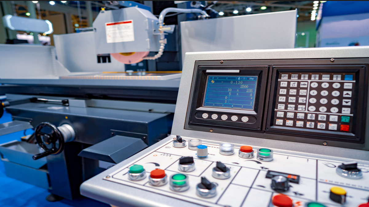
The five-axis controller is the core of the five-axis processing machine, which is used to control the trajectory of the five-axis simultaneous motion and the compensation of the motion.
The Development of Five-axis Machining Machines:
Precision machining is increasingly common in modern manufacturing. High-end CNC machine tools and molds that realize precision machining are at the forefront of the manufacturing industry chain, and the quality of mold products is largely controlled by CNC equipment. In the fierce market competition, the manufacturing industry requires shorter production cycles, higher processing quality, faster product modification processing adaptability, and lower manufacturing technology. To meet these conditions, more and more manufacturing companies have adopted high-end CNC machining tool machines, such as five-axis machining tool machines.
The five-axis linkage CNC machine tool system is the only means to solve the processing of impellers, blades, marine propellers, heavy generator rotors, steam turbine rotors, large diesel engine crankshafts, etc. It is a high-tech, high-precision machine tool specially used for processing complex curved surfaces. The machine tool system has a decisive influence on a country's aviation, aerospace, military, scientific research, precision instruments, high-precision medical equipment, and other industries.
What is a Five-axis Machine Tool?
A constrained tool or workpiece has six degrees of freedom in space. In fact, in the process of metal cutting, huge cutting force and friction force will be generated between the workpiece and the tool. To prevent the position of the workpiece from moving, the workpiece must be clamped and fixed. The commonly used three-axis machine tool has only three orthogonal motion axes, and can only achieve linear movement degrees of freedom in three directions. Therefore, the structure along the machining tool axis direction can be machined, and the side structure features cannot be machined.
Five-axis CNC machining means that there are at least five-coordinate axes on a machine tool, including three linear coordinates and two rotary coordinates, and can be processed simultaneously with coordinated movements under the control of a computer numerical control system. The axis of the CNC machine tool is used as a motion axis, which is a coordinate axis in space, such as the XY axis of the coordinates. There is no motion axis with an independent controller and motor drive system. That is, the CNC machine tool has 5 servo axes (excluding the main shaft) that can perform interpolation at the same time, and the 5 servo axes can move at the same time to process apart.
The Structure of the Five-axis Machine Tool:
There are many different structural forms of five-axis CNC machine tools, which are mainly divided into table tilting type, spindle tilting type, and table/spindle tilting type five-axis machining tool machine. The five-axis milling machine processing controller can roughly divide the control of each motion axis of the machine into two control methods: axis coordinate control and workpiece coordinate control.
- Table tilt type:
The worktable set on the bed can rotate around the X-axis, which is defined as the A-axis, and the A-axis generally has a working range of +30 degrees to -120 degrees. There is also a rotary table in the middle of the worktable, which revolves around the Z-axis in position, which is defined as the C-axis, and the C-axis rotates 360 degrees. In this way, through the combination of the A-axis and C-axis, except for the bottom surface of the workpiece fixed on the table, the other five surfaces can be processed by the vertical spindle.
The minimum division value of the A-axis and C-axis is generally 0.001 degrees, which can subdivide the workpiece into any angle, and process inclined surfaces, inclined holes, etc. If the A axis and the C axis are linked with the XYZ three linear axes, complex spatial surfaces can be processed, which requires the support of a CNC system, servo system, and software. The advantages of this arrangement are that the structure of the spindle is relatively simple, the rigidity of the spindle is good, and the manufacturing cost is relatively low. However, generally, the worktable cannot be designed too large, and the load-bearing capacity is also small, especially when the rotation of the A-axis is greater than or equal to 90 degrees, the workpiece cutting will bring a large load-bearing moment to the worktable.
- Spindle tilt type:
The front end of the spindle is a rotary head, which can revolve around the Z-axis 360 degrees by itself to become the C-axis. The rotary head also has an A-axis that can rotate around the X-axis, generally up to ±90 degrees or more, to achieve the same function as above. The advantage of this setup is that the machining of the spindle is very flexible, and the worktable can also be designed to be large. The huge fuselage of the passenger plane and the huge engine casing can be processed at this type of machining center.
The design advantage is that when the spherical milling cutter is used to process the curved surface when the tool center line is perpendicular to the processing surface. The surface quality of the workpiece cut out by the vertex will be poor because the linear velocity of the vertex of the spherical milling cutter is zero. The design makes the spindle rotate at an angle relative to the workpiece, so that the spherical milling cutter avoids the vertex cutting, and ensures a certain linear speed, which can improve the surface processing quality. This structure is popular for high-precision surface machining of molds, which is difficult to achieve with rotary machining centers. To achieve the high precision of rotation, the high-grade rotary shaft is equipped with a circular grating scale feedback, and the indexing accuracy is within a few seconds. The rotary structure of this type of spindle is relatively complex, and the manufacturing cost is high.
- Table/spindle tilt type:
The rotation axis configuration of this equipment is that the B axis and the table are combined around the C axis. One rotation axis is on the tool side of the spindle head, and the other is on the table side. This type of machine tool has maximum flexibility in the arrangement of the rotary axes, which can be any combination of any two of the A.B.C axes. The spindle of this type of machine tool can be rotated into a horizontal state and a vertical state, and the worktable can be simply configured as a three-axis machining center for vertical and horizontal conversion by indexing and positioning. Indexing, realizes pentahedron processing on the workpiece, has low manufacturing cost and is more practical.
What Applications Can the Five-axis Machine Tool Have?
The five-axis linkage machining center is suitable for processing complex, multi-process, high-demand, common machine tools and many tool holders that require various types, and can only be processed after multiple clamping and adjustment.
- Box parts:
Box-type parts generally require multi-station porosity and plane processing, with high tolerance requirements, especially the geometric tolerance requirements are relatively strict, usually need to go through milling, drilling, expanding, boring, reaming, tapping and other processes, need tools it is difficult to process on ordinary machine tools, requiring multiple clamping and alignment, and it is difficult to guarantee the machining accuracy. When machining box-type parts, it is necessary to rotate the worktable several times to process four sides in the horizontal direction, and it is suitable to use a horizontal machining center.
- Complex Surfaces:
Complex surfaces play an important role in machinery manufacturing, especially in the aerospace industry. It is difficult or even impossible to complete complex surfaces by ordinary machining methods. Complex surface parts such as various impellers, spherical surfaces, various surface forming abrasives, propellers, and propellers of underwater vehicles, and some other free-form surfaces. A five-axis machining center is most suitable for such parts. The milling cutter acts as an envelope surface to approximate the spherical surface. When the complex surface is processed by the machining center, the programming workload is large, and most of them must have automatic programming technology.
- Special-shaped parts:
Special-shaped parts are parts with irregular shapes, and most of them need multi-station mixed processing of point, line, and surface. The rigidity of special-shaped parts is generally poor, the clamping deformation is difficult to control, the machining accuracy is difficult to guarantee, and even some machining parts of some parts are difficult to complete with ordinary machine tools. When processing with a machining center, reasonable technological measures should be adopted, one or two clamping, and the characteristics of multi-station point, line, and surface mixed processing in the machining center should be used to complete multiple processes or all process contents.
- Disc cover plate parts:
With keyway, radial hole, or distributed hole system on the end face, curved disk sleeve or shaft parts, such as flanged sleeve, shaft parts with keyway or square head, etc., there are many holes processed plate parts, such as various motor covers, etc. Vertical machining centers should be selected for disc parts with distributed holes and curved surfaces on the end faces, and horizontal machining centers with radial holes.
- Special processing:
After mastering the functions of the machining center, with certain tooling and special tools, the machining center can be used to complete some special process work, such as lettering, engraving, and patterning on the metal surface. A high-frequency electric spark power supply is installed on the main shaft of the machining center to perform line scanning surface quenching on the metal surface. The high-speed grinding head is installed on the machining center, which can realize the grinding of small modulus involute bevel gears and the grinding of various curves and surfaces.
Machine Tool Control Technology Development Plan:
- Intelligent machine operation: Intelligent human-machine interface, multi-axis high-speed dynamic control, 3D solid anti-collision, and other multi-layer safety protection mechanisms.
- Multi-task composite automation technology: Multi-system simultaneous processing, automatic loading and unloading, and workpiece positioning turning/milling/drilling/grinding composite processing process and other functions.
- IT technology integration: It is divided into CCD visual correction (image capture, style recognition, and data conversion), and IT technology integration (vertical integration of upper and lower processes, built-in CAD/CAM system, and automatic parameters are automatically imported when drawing files are imported.) and other two major functions. Integrate intelligent machine operation, multi-tasking composite automation functions, and IT technology to build the next-generation Industry 4.0 intelligent control system, and achieve the goal of improving single-machine processing efficiency and overall plant productivity with intelligent functions.


.jpg)



.png)
