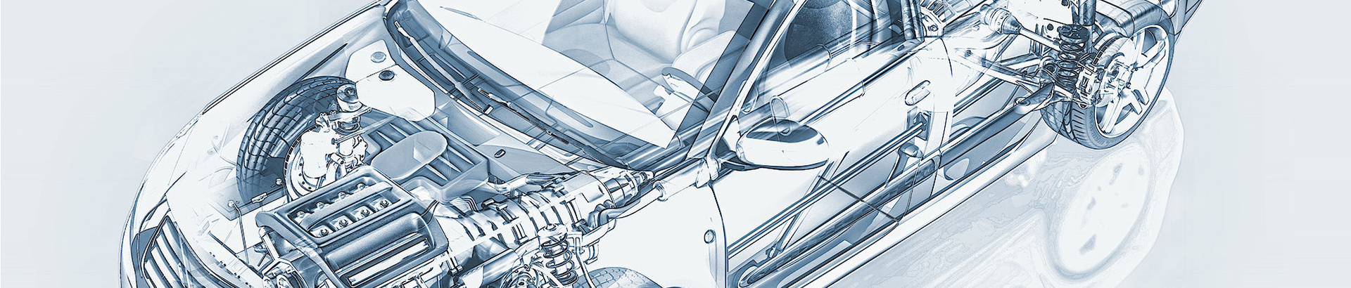
An automobile transmission system refers to the general term of all power transmission devices from the engine to the driving wheels. The function of the transmission system is to transmit the power of the engine to the driving wheels.
What is a automobile power transmission system?
Different cars have slightly different chassis compositions. For example, in trucks and some cars, their chassis is generally composed of clutches, transmissions, universal transmissions (universal joints and driveshafts), and drive axles (main reducers, differentials). It is composed of a motor, half shaft, axle housing) and so on. However, more and more automatic transmissions are used in modern cars, and their chassis includes automatic transmissions, universal transmissions, drive axles, etc., that is, automatic transmissions are used to replace clutches and manual transmissions. If it is an off-road vehicle (including SUV, (Sports Utility Vehicle), it should also include the transfer case.
Power transmission system-the concept of integrated intelligent control of automobile power transmission system integrated control:
The integrated control of the automobile power transmission system refers to the application of electronic technology and automatic transmission theory. With the electronic control unit (ECU) as the core, through the hydraulic actuator to control the separation and engagement of the clutch, the selection and shifting operations, and the control of the engine through the electronic device, the oil supply realizes the automatic operation of starting and shifting. The basic control idea is: according to the driver's intention (accelerator pedal, brake pedal, joystick, etc.) and the state of the vehicle (engine speed, input shaft speed, vehicle speed, gear position), and according to the appropriate control law (shift Rules, clutch engagement rules, etc.), with the help of corresponding actuators (clutch actuators, shifting actuators) and electronic devices (engine fuel supply control electronic devices,) the vehicle powertrain (engine, clutch, transmission) will carry out joint manipulation.
Integrated control method
The integrated control mode of the power transmission system is generally divided into 3 categories:
- Use two or more computers to communicate. Realize information sharing between engine ECU and transmission ECU. This kind of control method makes full use of mature engine and transmission control technology, makes few changes to the original system, is easy to implement, and has low development costs, but due to more wiring, the integration is not high.
- A single ECU is used to achieve overall control of the engine and transmission. Its advantages are high integration, reduced peripheral wiring, and improved reliability, but it has higher requirements for ECUs and high development costs. The power control system on the Toyota Lexus Ls400 sedan, the four-speed automatic transmission A341 E with intelligent control system, and the engine all use the same ECU. The ECU, equipped with a microcomputer, controls the automatic transmission shifting, locking time, and the actuator in the planetary gear system. It also controls the clutch, brake, oil pressure and engine torque when shifting gears, making for maximum quality shifting.
- Adopt CAN bus structure for overall control. At present, the CAN bus is widely used in automobiles, and the structure of the two control subsystems of the engine and the transmission through the CAN bus is shown in Figure 2. Through the CAN bus, the two systems can not only transmit commands, requests, and some basic states of the car (such as engine speed, vehicle speed, cooling water temperature, etc.) but also transmit real-time data such as fuel volume and speed signals, setting higher priority commands and so on.
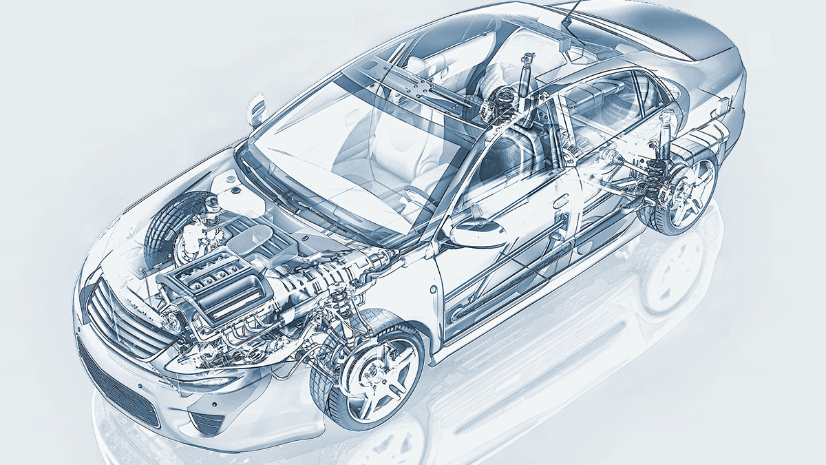
The architecture of the automobile power transmission system
The basic composition of the integrated control system of the automobile power transmission system
The function of the control system is to automatically adjust the transmission ratio and working status of the basic transmission components according to the driver's intention and the changes in the vehicle driving environment, to achieve the best transmission efficiency and the best overall vehicle performance. The vehicle control system is mainly composed of three parts: the vehicle data acquisition system (sensor part), the electronic control unit, and the actuator.
- The composition of the vehicle data acquisition system (sensor part). In the entire control system, part of the role of the sensor is equivalent to the driver's visual, auditory, and tactile system in the case of manually operating the shifting vehicle, collecting, and transmitting various parameter signals required for shifting to the electronic control unit.
The vehicle runs and works according to the driver's intention, and the vehicle control system must be able to correctly recognize and implement the driver's manipulation. The recognition of the driver's intention is to test the changes of the vehicle control mechanism (such as accelerator pedal, brake pedal, steering wheel angle, etc.) through sensors, and obtain through analysis.
The sensors used in automobiles mainly include the following types: magnetoelectric sensors, magneto resistive sensors, photoelectric sensors, Hall sensors, thermal sensors, varistor sensors, piezoelectric crystal sensors, etc. The sensors used in the transmission part of the power transmission system mainly include engine speed sensor, vehicle speed sensor, throttle opening sensor, clutch displacement sensor, etc. Among them, the engine speed sensor and the vehicle speed sensor use magnetoelectric sensors and Hall sensors, and other sensors that use the principle of magnetoelectric signals. The throttle opening sensor and the clutch displacement sensor both use rheostat sensors.
In addition to sensors, other signals are transmitted through switches and controllers or other methods. Commonly used switches include multi-function switches and forced low-shift switches. The switch is also a very important means of signal input.
- Electronic control unit. The electronic control unit (ECU) is the core of the entire control system. Its function is based on the driver's intention and the signal detected and provided by the vehicle's motion state parameters to carry out gear shifts or working state changes. The main functions of the electronic control unit are: signal acquisition and preprocessing, driver manipulation intention recognition, vehicle status recognition, shift decision (shift schedule), shift quality control, fault diagnosis function, output, and display functions.
The new generation of controllers has comprehensive functions and very good control performance. It uses high-performance 16-bit or 32-bit microprocessors, and some even use custom-made microprocessors, which contain most of the functions required for control and simplify control of the circuit and enhance the function and reliability of the circuit. As the controller's microprocessor is updated, the shift control is more complicated, and the processor's peripheral circuit expansion makes the input and output functions more powerful. In order to achieve greater improvement in control performance, not only control programs are used in these controllers, but also embedded real-time operating systems are used.
- Executive agency. After the control system samples and obtains the input signal, it is sent to the controller for data processing. After the data processing is completed, control signal No. 1 of the electronic control unit will change the working state of the power transmission system through the actuator to ensure the proper performance of the vehicle. At the same time, the actuator guarantees the control of shift quality. The actuators that realize gear switching generally use solenoid valves.
The composition of the transmission system:
The mechanical transmission system is mainly composed of clutch, transmission, universal transmission, and drive axle. The universal transmission device is composed of a universal joint and a drive shaft, and the drive axle is composed of the main reducer and a differential.
The hydromechanical transmission system is mainly composed of a hydraulic torque converter, an automatic transmission, a universal transmission, and a drive axle.
The function of the transmission system:
- Deceleration and torque increase: The power output by the engine has the characteristics of high speed and low torque, which cannot meet the basic needs of car driving. Through the main reducer of the transmission system, the purpose of deceleration and torque increase can be achieved, which is transmitted to the driving wheels. The lower torque of the engine is converted to higher torque of the drivetrain.
- Variable speed and torque: The optimal working speed range of the engine is very small, but the speed of the car and the resistance that needs to be overcome vary in a wide range. Through the transmission system, the working range of the engine can be expanded, thereby meeting the demands for large changes in the driving speed of the car and overcoming various driving circumstances and resistance.
- Reversing: The engine cannot be reversed, but in addition to forwarding, the car needs to reverse. If the reverse gear is set in the transmission, the car can reverse.
- Interrupt the power transmission of the transmission system when necessary: When starting the engine, shifting gears, stopping for a short time during driving (such as waiting for a traffic light), or car sliding at low speed, it is necessary to interrupt the power transmission of the transmission system. The neutral gear can interrupt the power transmission.
- Differential function: In the case of car steering, etc., the two driving wheels need to be able to rotate at different speeds, and the differential function can be realized through the differential in the drive axle.
The installation position of the automobile transmission system:
- Front-engine Rear-drive (FR) engine is mainly used for trucks, some passenger cars, and some luxury cars.
- Front-engine Front-drive (FF) is a layout that is gradually prevailing on cars. It has the advantages of compact structure, reduced vehicle weight, lowered floor height, and improved handling stability at high speeds.
- Engine transverse: the axis of the crankshaft of the engine is parallel to the axis of the wheels, and the main reducer can be driven by cylindrical gears.
- Longitudinal installation of the engine: the axis of the crankshaft of the engine is perpendicular to the axis of the wheels, and the main reducer must be driven by a conical gear.
- Rear-engine Rear-drive (RR): The engine is arranged behind the rear axle and driven by the rear wheels. Mainly used in large and medium-sized passenger cars and a few sports cars.
- Middle-engine Rear-drive (MR): The engine is arranged between the front and rear axles and is driven by the rear wheels. Used in sports cars and a few large and medium passenger cars.
- All-wheel drive (AWD): A transfer case is added to the transmission system, and the power can be transmitted to the front and rear wheels at the same time. Mainly used for off-road vehicles and heavy trucks.
The function of the transmission system is to connect the engine that generates power and the drive wheel, which uses mechanical energy to rotate the shaft of the drive wheel. The coupling also includes two physical elements, and on the vehicle, they may not be in proximity, so a long driveshaft is required. The speed of the engine and the driving wheels are different, so a gear train is needed to convert the speed.