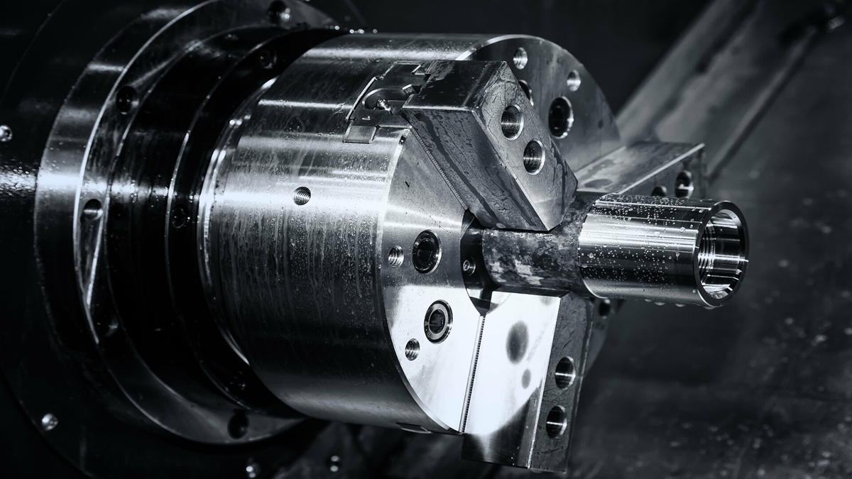
Gears are mechanical parts with teeth that mesh with each other to transmit motion and power in mechanical equipment. Because the ratio of transmission in gears is set, their perfect accuracy makes them ideal for precision machinery.
What is A Gear?
Gears are mechanical parts with teeth that mesh with each other to transmit motion and power in mechanical applications. Of all mechanical transmission applications, gear transmission is the most widely used.
There are many kinds of gears, and the most common classification method is according to the gear shaft. Generally, gears are divided into three categories: parallel axis, intersecting axis, and staggered axis.
Parallel Axis Gears
These include spur gears, helical gears, internal gears, racks and helical racks, etc.
Intersecting Axis Gears
These include straight bevel gears, spiral bevel gears, zero-degree bevel gears, etc.
Staggered Axis Gears
These include staggered shaft helical gears, worm gears, hypoid gears, etc.
What is Gear Transmission?
Gear transmission is the mechanism of using toothed wheels that mesh in various arrangements to change direction and speeds of rotating mechanical operations. In gear transmission one gear acts as the drive or driving gear and the other one as the driven gear.
Features of Gear Transmission
Efficient
Among the commonly used methods for transmission of mechanical force, gear transmission has the highest efficiency. Transmission efficiency is usually 96%~99%, making it highly suitable and economical for heavy mechanical applications.
Compact
The space size required for gear interfaces is small.
Stable Transmission
Transmission of force through gears is very stable, so gear transmission is widely used for many mechanical applications.
Reliable Performance and Long Life
When gear transmissions are designed, manufactured, and maintained correctly, they have a very reliable service life and can be used as long as ten or twenty years. This is especially important for vehicles and machines that operate continuously for long periods of time such as in mines. However, the manufacturing costs and precision required for gear transmission are relatively high, and they are not suitable for applications where the transmission distance is too far.
Classifications of Gear
Gear types can be divided according to their method of force transmission. The method of force transmission of cylindrical gears, bevel gears, rack gears, and worm gears differs according to the shape of the gear.
Cylindrical Gears
Cylindrical gears transmit motion and power between parallel shafts. Cylindrical gears can be divided into three types according to the relative relationship between the gear teeth and the gear axis. Cylindrical gears types include: spur gears, helical gears, and herringbone gears.
The teeth of spur gears are parallel to the axis, so the contact line of the tooth surface is a straight line. During meshing, the entire tooth width enters and exits meshing at the same time, so the force is suddenly added or removed. This causes poor transmission stability and sometimes loud noise from the impact during meshing.
Helical gears are similar to spur gears except that their teeth are cut at an angle to the axis. During meshing, the initial contact point sweeps across the length of the tooth as it turns, making a smoother transmission of force. One consequence of the offset angle is the production of a side thrust on the axis.
Herringbone gears, like helical gears, have teeth set at an angle to the axis, but instead of a single set of teeth with the angle in one direction, there is a pair of parallel gears with teeth angled equally and opposite to each other. The parallel rows of teeth counterbalance each other’s side thrust, so that herringbone gears will not have a side thrust.
The transmission power and speed of cylindrical gear makes them suitable for a wide range of applications. Power can be from as small as one thousandth of a horsepower, to as high as 100,000 horsepower, with speeds as high as 300 meters per second.
Bevel Gears
Bevel gears transmit force between intersecting shafts which are set at an angle to each other. Bevel gears can have teeth which are straight beveled, similar to spur gears, or have spiral beveled teeth similar to helical gears. Both straight bevel and spiral bevel gears are widely used.
Rack Gears
Rack gears convert rotational motion into linear motion. A cylindrical gear (called a pinion) meshes with a straight linear gear, (called a rack) to apply force in a straight line. Rack and pinion gears use both straight and helical gears, but side force created by helical gears can create problems leading to premature wear, so straight, spur gears are more commonly used.
Worm Gears
A worm gear is a gear consisting of a shaft with a spiral thread called the worm, similar to the threads of a bolt or screw, that meshes with the teeth of a toothed gear. As the worm is rotated, it pulls (or pushes) the toothed gear, similar to the way a bolt or screw pulls its way into the material it is holding together. A common application of a worm gear is the adjustment knobs on musical stringed instruments.







.png)
