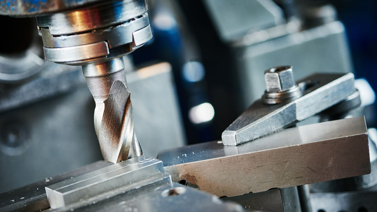
When selecting a milling cutter suitable for the machining task, various issues such as the geometry, size, and work piece material of the parts to be processed must be considered.
Choosing a milling process
Choosing the right milling tool, using rolling cutting in face milling, and using a milling cutter for hole machining when conditions are right, manufacturers can significantly increase production capacity and increase processing efficiency without investing in new equipment, which saves a lot of time and cost.
Milling cutter main angle:
The declination angle is the angle between the cutting edge and the cutting plane. The main declination angle has a great influence on the radial cutting force and cutting depth. The magnitude of the radial cutting force directly affects the cutting power and the vibration resistance of the tool. The smaller the main declination angle of the milling cutter, the smaller the radial cutting force and the better the vibration resistance, but the cutting depth also decreases.
When milling the plane with square shoulders, select a 90° lead angle. This kind of tool has good versatility and is used in a single piece and small-batch processing. Because the radial cutting force of this type of tool is equal to the cutting force, the feed resistance is large and it is easy to vibrate, so the machine tool is required to have greater power and sufficient rigidity.
When machining a flat surface with a square shoulder, a milling cutter with an 88° main angle can also be used. Compared with the 90° main declination milling cutter, its cutting performance has been improved. Face milling with 90° square shoulder milling cutters is also very common. In some cases, this choice makes sense. The shape of the milled work piece is irregular, or the surface of the casting will cause the depth of cut to change. A square shoulder milling cutter may be the best choice. But in other cases, the standard 45° face milling cutter may benefit more.
When the cutting angle of the milling cutter is less than 90°, the thickness of the axial chip will be smaller than the feed rate of the milling cutter due to the thinning of the chip. The cutting angle of the milling cutter will have a great influence on the applicable feed per tooth.
In face milling, a face milling cutter with an angle of 45° will make the chips thinner. As the cutting angle decreases, the chip thickness will be less than the feed per tooth, which in turn can increase the feed rate to 1.4 times the original. The radial cutting force of the 45° main declination milling cutter is greatly reduced, which is approximately equal to the axial cutting force. The cutting load is distributed on the longer cutting edge. It has good vibration resistance and is suitable for the overhang of the spindle of the boring and milling mac hine. Longer processing occasions. When machining flat surfaces with this type of tool, the blade breakage rate is low and the durability is high; when machining cast iron parts, the edges of the work piece are not prone to chipping.
Selection of milling cutter size:
The diameter of the standard index able face milling cutter is Φ16~Φ630mm. The diameter of the milling cutter should be selected according to the milling width and depth. Generally, the larger the depth and width before milling, the larger the diameter of the milling cutter. During rough milling, the diameter of the milling cutter of the milling machine is smaller; when finishing milling, the diameter of the milling cutter is larger, as far as possible to accommodate the entire processing width of the work piece and to reduce the traces of tool connection between two adjacent feeds.
When face milling large parts, they use milling cutters with smaller diameters, which leaves much room for improving productivity. In an ideal situation, a milling cutter should have 70% of the cutting edges involved in cutting. When milling holes with a milling cutter, the tool size becomes particularly important. Compared with the hole diameter, the diameter of the milling cutter is too small, then a core may be formed in the center of the hole during processing. When the core falls, it may damage the work-piece or tool. If the diameter of the milling cutter is too large, it will damage the tool itself and the work piece, because the milling cutter is not cutting in the center and may collide at the bottom of the tool.
Selection of milling method:
Another way to improve the milling process is to optimize the milling strategy of the face milling cutter. When programming surface milling, the user must first consider the way the tool cuts into the work piece. Usually, the milling cutter simply cuts directly into the work piece. This cutting method is usually accompanied by a large impact noise because when the insert is withdrawn, the milling cutter produces the thickest chips. Because the blade forms a large impact on the work piece material, it often causes vibration and produces tensile stress that will shorten the life of the tool.
A better way to feed is to use the rolling cutting method, that is, without reducing the feed rate and cutting speed, the milling cutter rolls into the work piece. This means that the milling cutter must rotate clockwise to ensure that it is processed in a milling manner. The chips formed in this way are from thick to thin, which can reduce vibration and tensile stress on the tool, and transfer more cutting heat to the chips. By changing the way, the milling cutter cuts into the work piece each time, the tool life can be extended by 1-2 times. To achieve this in-feed method, the programming radius of the tool path should be 1/2 of the diameter of the milling cutter, and increase the offset distance from the tool to the work piece.
Although the rolling cutting method is mainly used to improve the way the tool cuts into the work piece, the same machining principle can also be applied to other stages of milling. For large-area plane milling, the commonly used programming method is to let the tool pass through the entire length of the work piece one after another and complete the next cut in the opposite direction. To maintain a constant radial tool intake and eliminate vibrations, the use of a combination of helical lower knife and rolling milling work piece corners usually results in better results.
Mechanics are familiar with the cutting noise caused by vibration. It usually occurs when the tool cuts into the work piece, or when the tool makes a sharp 90° turn while eating. Roll milling of work piece corners can eliminate this noise and extend tool life. In general, the corner radius of the work piece should be 75%-100% of the diameter of the milling cutter, which can shorten the arc length of the milling cutter and reduce vibration, and allow the use of higher feed rates.
To prolong the life of the tool, in the face milling process, the tool should be avoided as far as possible from the hole or interrupted part of the work piece (if possible). When the face milling cutter passes through the middle of a hole in the work piece, the cutter is milled along one side of the hole and the reverse milling is performed on the other side of the hole, which will cause a great impact on the insert. This can be avoided by bypassing holes and pockets when programming the tool path.
Use down milling or up milling:
More and more manufacturers use milling cutters to machine holes in helical or circular interpolation. Although the processing speed of this method is slightly slower than that of drilling, it is more advantageous for many processes. When drilling holes on irregular surfaces, it may be difficult for the drill bit to drill into the work piece along the center line, causing the drill bit to drift on the work piece surface. Besides, the drill bit requires about 10 horsepower for each 25mm hole diameter, which means that when drilling on a small power tool, the optimal power value may not be achieved. Also, some parts need to process many holes of different sizes. If the tool magazine's tool magazine capacity is limited, the use of milling holes can avoid a frequent shutdown of the machine tool due to tool replacement.
When milling holes with a milling cutter, the tool size becomes particularly important. If the diameter of the milling cutter is too small relative to the hole diameter, a core may be formed in the center of the hole during machining. When the core falls, it may damage the work piece or tool. If the diameter of the milling cutter is too large, it will damage the tool itself and the work piece, because the milling cutter is not cutting in the center and may collide at the bottom of the tool.
To prolong the life of the tool, in face milling, the tool should be avoided as far as possible from the hole or interrupted part on the work piece. When the face milling cutter passes through the middle of a hole in the work piece, the cutter is milled along one side of the hole and the reverse milling is performed on the other side of the hole, which will cause a great impact on the insert. This can be avoided by bypassing holes and pockets when programming the tool path.
By selecting the appropriate milling cutter angle, size and feed method, the tool can cut into the work piece material with minimum vibration and tensile stress, and know under which circumstances milling holes is more effective than drilling, and manufacturers can be highly efficient, Low-cost processing of work piece blanks into exquisite parts.


(4059)(20260924)(原).jpg)
(2367)(20260924)(原).jpg)