Why Precision Manufacturing Depends on More Than Machine Accuracy
A precision machine can repeat the same motion thousands of times, but its performance also depends on how parts arrive at the work area. If components are misaligned, held at inconsistent heights, or delayed between operations, the precision of the machine alone cannot ensure a consistent result.
This challenge is particularly visible in passive component manufacturing, where large numbers of small chips must be positioned for termination dipping. Equipment, carrier plates, transfer tooling, paste application, and drying all influence the flow of production. A problem at one interface can affect the next operation, even when each item appears suitable on its own.
For manufacturers planning automation, the question is therefore expanding from “Which machine should we buy?” to “How will the machine, carrier, and surrounding processes work together?”
Why a Faster Machine Does Not Always Mean a Better Production Flow
An automatic dipping machine may have an impressive published capacity, but the production line still depends on loading, insertion, carrier preparation, drying, unloading, and inspection. If a carrier needs frequent adjustment or a downstream station cannot accept the output, a faster dipping cycle may simply create more work in process.
The same applies to quality. A machine can repeat a programmed movement, but the amount of paste applied also depends on component position, carrier condition, paste properties, and process settings. When these variables are considered separately, troubleshooting becomes more difficult: a defect may be attributed to the machine when its origin lies in the carrier, material, or transfer step.
For this reason, manufacturers should evaluate the complete production workflow—from loading and carrier positioning to dipping, transfer, and inspection—to identify the steps that limit output or affect quality. This provides a clearer basis for deciding where integration or automation will deliver the most value.
The Carrier Plate Is Part of the Process
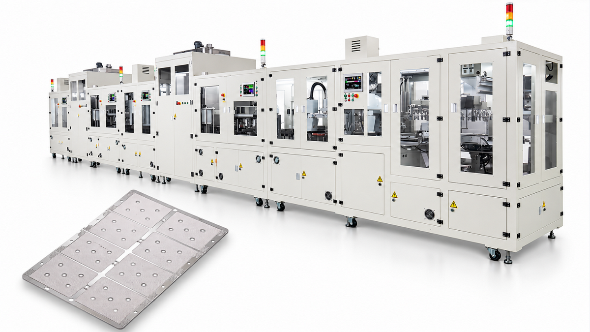
A carrier plate is more than a way to transport parts. It holds chips in a defined arrangement as they move through production. Its hole dimensions and layout must suit the component, while the plate itself must interface with the equipment and associated tooling.
For termination dipping, a chip's position in the carrier affects how its exposed end meets the paste. Differences in seating height, orientation, or plate condition can contribute to variation in the applied termination. The dipping mechanism and carrier therefore need to be evaluated together, along with the paste and the component itself.
The appropriate carrier depends on the application. A thin carrier plate (TCP), for example, can be used with dedicated TCP dipping equipment. Other carrier designs may suit different chip geometries or existing production lines. Plate choice should be based on confirmed fit and trial results, not on the assumption that one carrier works across every machine or product.
From Individual Equipment to a Connected Workflow
In a typical chip termination process, the workflow begins before the dipping motion and continues after it:
- Loading and insertion: Chips are arranged and placed in the carrier. Hole fit, orientation, and insertion height need to be suitable for the component.
- Preparation and dipping: The carrier is positioned for contact with conductive paste. Machine settings and paste condition influence the deposit.
- Drying and transfer: Coated parts move through the relevant drying and handling steps while maintaining the required process conditions.
- Unloading and inspection: Parts leave the carrier and are assessed against the manufacturer's quality criteria. Carriers are then cleaned or checked before reuse.
The exact sequence and degree of automation depend on the equipment configuration and product requirements. In MLCC manufacturing, termination dipping is part of the external-electrode process; subsequent steps include termination firing, plating, and testing.
Coordinating these interfaces can help manufacturers identify where parts are waiting, where handling introduces variation, and which stations require the most attention. It does not remove the need to validate the complete process with the manufacturer's own chips and materials.
What Machine-and-Carrier Integration Can Improve
More consistent positioning
A dipping head's movement is only one part of the positioning system. Carrier flatness, hole geometry, chip dimensions, and insertion method also affect the relationship between each part and the paste surface. Designing and checking these elements together gives process engineers a clearer basis for controlling the dipping operation.
Consistency must still be measured. Manufacturers should inspect representative positions across the carrier and define acceptable termination geometry and defect limits for each product.
Fewer uncertain handoffs
Each transfer between a loading fixture, carrier, machine, and unloading station creates an interface to manage. When dimensions and handling methods are coordinated, manufacturers can more readily check how parts enter and leave each step, what happens during a stoppage, and where manual intervention is required.
Integration does not necessarily mean a completely unattended factory. Depending on the configuration, operators may still load carriers, replenish materials, inspect parts, maintain equipment, and respond to alarms. The aim is to make those responsibilities clear and support a stable flow.
A more practical approach to product changes
A new component size can affect more than a machine recipe. It may require a different carrier hole pattern, insertion tooling, transfer method, or paste setting. Evaluating the machine and carrier as a system helps manufacturers identify those dependencies before adding a new product.
A useful starting point is a compatibility matrix listing each chip's dimensions, carrier and tooling versions, process recipe, and required changeover steps. The plant can then test its most common and most demanding products rather than assuming that a published size range covers every variation.
Better visibility into usable output
Nominal speed alone does not describe the number of acceptable parts a line can produce. A production review should also consider loading losses, defects, downtime, cleaning, and changeover. Measuring first-pass accepted output over an agreed period gives buyers and engineers a more useful basis for comparing configurations.
How LONG's Machine and Carrier Portfolio Illustrates the Approach
LONG Automatic Machinery Co., Ltd. offers equipment and carrier products for passive component termination, providing a concrete example of the machine-and-carrier ecosystem.
Its LGTM-6837 TCP Full Automatic Single Side Dipping Machine is listed for chips of 0402 inch and above. According to LONG, its process includes automatic loading and insertion into TCPs, dipping, vacuum debubbling, drying, transfer, and unloading. The machine illustrates how several operations can be connected around a carrier-based workflow. “Single side” refers to the end coated in that pass; the process for the opposite end and subsequent operations must be planned separately.
LONG also lists the LGTM-6168 TCP Auto Dipping Machine, where TCPs are placed on the machine by an operator. Its published description covers different single-side or two-side processes depending on chip size. This distinction shows why buyers should confirm the actual operating boundary and staffing requirements of each model.
For multiple-terminal applications, the LGTM-3968 Array Automatic Dipping Machine uses an array thin carrier plate, or ATCP. LONG's associated equipment list also includes insertion, press, transfer, and unloading items. These examples demonstrate different configurations rather than interchangeable components: the machine, carrier, and tooling must be matched to the application.
Alongside TCP products, LONG lists CP carrier plates using silicone and aluminum, with models and customization options for different chip and equipment requirements. Compatibility with an existing line should be confirmed using the chip drawing, carrier dimensions, and machine model.
What Should Manufacturers Evaluate Before Investing?
A machine-and-carrier project starts with the production requirements, not a catalog selection. The following questions can help align the process, purchasing, and maintenance teams:
| Area |
Questions to address |
| Component and product mix |
What are the chip dimensions, tolerances, target volumes, and expected future sizes? Are size codes specified in inch or metric units? |
| Carrier and tooling |
Which carrier, hole pattern, loading plate, and transfer tooling are required for each product? How are wear, cleaning, and replacement managed? |
| Process boundary |
Which loading, dipping, drying, transfer, and unloading steps are included? How will the opposite termination end and downstream operations be handled? |
| Quality and capacity |
What termination measurements and defect limits apply? What first-pass accepted output can be demonstrated with the intended chips and paste? |
| Operation and support |
What operator tasks, changeovers, utilities, maintenance access, spare parts, and training are needed? |
Before committing to a configuration, request a production trial or factory acceptance test using representative components, carrier plates, and paste. Agree on the run duration, inspection method, acceptance criteria, and how downtime and rejected parts will be counted. A measured result under those conditions is more informative than a headline machine speed.
Building Around the Complete Production Requirement
Machine-and-carrier integration is becoming more important because precision manufacturing depends on the relationship between operations as well as the accuracy of individual machines. A well-matched carrier supports part positioning and handling; a suitable machine applies the intended process; and coordinated transfer, drying, inspection, and maintenance help the line operate as a system.
For manufacturers of passive components, this broader view creates a practical way to assess automation: define the product and quality requirements, map the full workflow, and verify performance using the intended materials and tooling. Explore LONG Automatic's integrated automatic dipping machine and carrier plate portfolio.