How Tube Preparation, Incomplete Insertion, and Side Loading Affect Pneumatic Sealing Reliability
Push-in pneumatic fittings make air-line assembly fast, but speed can hide small installation errors. A fitting may look correctly assembled and still hiss, lose pressure, or leak only when the machine moves. In many cases, the connector itself is not defective. The problem is the interface between the fitting and the tube—especially the quality of the cut, how far the tube is inserted, and whether the tube is pulling sideways on the joint.
These three factors are closely linked. A damaged tube end can compromise the seal, incomplete insertion can leave the tube short of its intended sealing position, and side load can disturb a connection that initially passed a leak check.
How a Push-In Connection Seals
A typical push-in fitting uses a gripping element to retain the tube and an elastomeric seal around the tube's outside diameter. The tube therefore needs the correct size, a sound outer surface, and sufficient insertion depth. ISO 14743:2020 establishes general requirements and test methods for push-in connectors used with thermoplastic tubes in pneumatic fluid-power applications.
The practical lesson is simple: troubleshooting should consider the tube and installation method as part of the sealing system, not just the fitting body.
1. Tube Preparation: Small Cutting Errors Matter
Manufacturers commonly specify a square or perpendicular tube cut and warn against damaging the outside surface. SMC notes that unsuitable cutting tools can flatten or deform tubing and may contribute to poor installation, tube disconnection, or air leakage. Festo likewise instructs users to use straight, deburred tube ends.
A diagonal cut creates an uneven leading edge. A burr can scrape the internal seal during insertion, while an oval or crushed tube can prevent uniform contact around the outside diameter. Longitudinal scratches may also form a leakage path along the sealing zone.
Before insertion, inspect the tube end. It should be square, round, clean, and free from visible damage. A previously connected end that is deeply marked or deformed is better cut back to fresh tubing than simply pushed in again. Festo specifically recommends removing a damaged section before reusing tubing.
| Installation issue |
Effect at the joint |
Typical symptom |
| Angled or rough cut |
Uneven seal contact |
Immediate low-level leak |
| Flattened tube |
Non-uniform sealing |
Leak after reinsertion |
| Scratched tube OD |
Air path along tube surface |
Fine bubbling in leak test |
| Damaged reused end |
Old marks enter sealing zone |
Recurring leakage |
2. Insertion Depth: Resistance Is Not Always the Stop
A push-in connection has a defined insertion path. The tube passes the gripping mechanism, enters the sealing area, and continues to an internal stop. Festo specifically warns that contact with the seal can sometimes be mistaken for the final stop. Its instructions call for inserting the tube fully and then gently pulling it to confirm secure engagement.
This explains a common field failure: the installer feels resistance and stops too early. The tube may be retained mechanically without being positioned correctly through the sealing area. Vibration, pressure cycling, or later movement can then expose the weakness.
A useful method is to check the manufacturer's specified insertion depth and mark that distance on the tube before assembly. The mark provides a simple visual confirmation. Because insertion depth varies by fitting size and design, one universal dimension should not be applied to every connector; Festo's own QS specifications list different insertion depths depending on the fitting configuration.
If a newly installed joint leaks, depressurize the system before handling it. Remove the tube according to the fitting instructions, inspect or recut the end if necessary, and reinstall it to the full stop.
3. Side Load: When Routing Pulls the Joint Off-Axis
A fitting can be assembled correctly and still leak if the tube is forced sideways immediately after leaving the connector. This lateral or bending force is commonly described as side load.
It often appears in compact panels, moving equipment, or installations where tubing is slightly too short and must be stretched into position. A tight bend near the connector can transfer bending force directly into the tube-to-seal interface. SMC tubing guidance specifies minimum bending radii and cautions against routing that leaves tubing excessively bent or flattened.
Side-load leaks may be intermittent. A joint can pass a static test while the machine is idle, then leak when a cylinder moves, a door opens, or a hose bundle shifts. That behavior is an important diagnostic clue.
Better routing leaves a short neutral section of tube at the fitting, respects the tubing manufacturer's minimum bend radius, and avoids using the connector as a structural support. In tight spaces, an elbow or swivel fitting can be preferable to forcing a straight connector to accept a sharp bend.
A Practical Installation Sequence
Start with tubing that matches the fitting specification for material and outside diameter. Cut it with a suitable tube cutter, confirm that the end is square and undamaged, and deburr where required. Insert the tube straight until the true stop is reached, then perform a gentle pull check. Route the tube without tension or an immediate tight bend. These practices are consistent with installation guidance published by major pneumatic component manufacturers.
Finally, pressure-test the circuit under realistic operating conditions. Static leak testing can find many faults, but moving equipment should also be observed through its normal motion because side-load leakage may appear only dynamically.
FAQ
1. Can a push-in fitting leak even if the tube cannot be pulled out?
Yes. Retention and sealing are related but not identical functions. A tube can be gripped while still being poorly positioned or damaged at the sealing area.
2. Should pneumatic tubing be cut at 90 degrees?
For conventional push-in fittings, manufacturer instructions commonly call for a square or perpendicular cut. A dedicated tube cutter helps avoid angled cuts and flattening.
3. How can I verify insertion depth?
Use the fitting manufacturer's specified insertion depth when available. Marking the tube, pushing to the internal stop, and performing a gentle pull check provide practical confirmation.
4. Can I reuse the same tube end after disconnection?
Inspect it first. If it is scratched, deformed, or deeply marked, cut back to undamaged tubing before reconnecting. Festo specifically advises removing damaged tubing before reuse.
5. Why does the leak appear only when the machine moves?
Movement can change tube angle or tension. A side-loaded connection may seal while stationary but leak when the tube or hose bundle shifts.
6. Is a very tight bend acceptable if the tube still fits?
Not necessarily. Tubing has a recommended minimum bending radius. An overly tight bend can flatten the tube or transfer force into the fitting.
Conclusion
Leaks after push-in fitting installation are often interface problems rather than simple component failures. Three checks provide a strong starting point: inspect the tube end, confirm full insertion, and remove side load from the joint. Controlling these details makes troubleshooting faster and helps the assembled connection perform as intended.
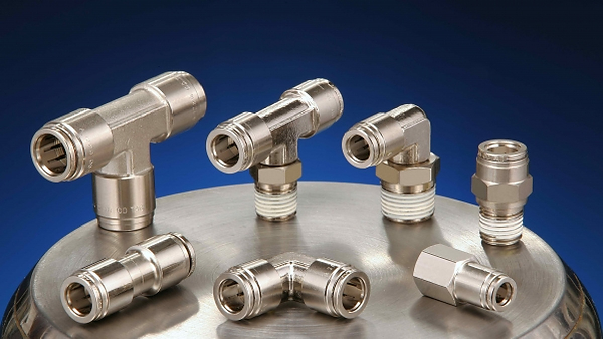
For engineers or buyers comparing metal push-in fitting options, Guang Yang offers nickel-plated brass push-in fittings in connector, union, elbow, and tee configurations. Reviewing different geometries can help match the fitting to the tube route instead of forcing the tubing into an unfavorable bend.

(4059)(20260924)(原).jpg)
(2367)(20260924)(原).jpg)