How Flow Path, Closure Geometry, Pressure Loss, and Operating Duty Influence Valve Selection
Gate valves and globe valves are both linear-motion valves, but their internal designs suit different jobs. A gate valve mainly creates a clear passage or a complete obstruction. A globe valve deliberately creates a more restrictive path so flow can be adjusted with greater control.
This distinction affects pressure loss, throttling, seat wear, operating force, and shutoff. Selection should begin with operating duty, not simply size or cost.
How a Gate Valve Works
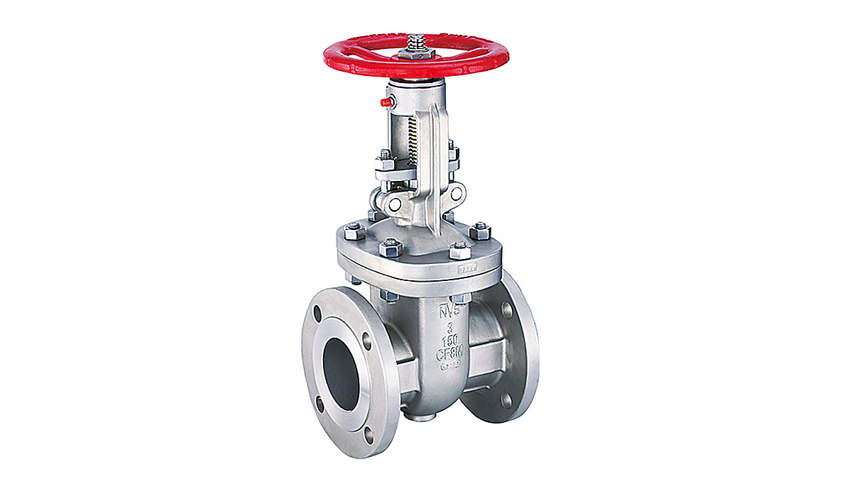
Inside a gate valve, a wedge-shaped or parallel gate travels perpendicular to the pipeline. When fully open, the gate is raised out of the flow path, leaving a relatively straight passage. In a full-port design, the opening may be close to the connected pipe’s internal diameter.
This geometry suits isolation service. Because the fully open valve presents limited obstruction, it generally creates less pressure loss than a comparable globe valve. They are common where valves remain fully open or fully closed for long periods.
The design is less suitable for throttling. When the gate is partly open, high-velocity fluid passes around its edge and across the seats. Turbulence may cause vibration, noise, erosion, or a cutting effect known as wire drawing. Repeated partial-open operation can damage the seating surfaces and reduce shutoff reliability.
How a Globe Valve Controls Flow
A globe valve uses a plug or disc that moves toward and away from a stationary seat. In many conventional designs, fluid changes direction inside the body before passing through the seat opening. This indirect route produces more resistance, so a globe valve usually has a higher fully open pressure drop.
The restrictive path enables regulation because plug shape and movement can create a predictable relationship between valve position and flow. Globe-style valves are therefore widely used to regulate flow, pressure, or temperature. Spirax Sarco notes that globe valves are frequently selected for control because they are suitable for throttling and can be designed with defined flow characteristics.
The plug approaches the seat axially, allowing the stem or actuator to apply closing force directly. Effective shutoff still depends on seat material, differential pressure, temperature, fluid cleanliness, actuator capability, testing requirements, and wear.
Main Performance Differences
| Selection factor |
Gate valve |
Globe valve |
| Primary role |
On-off isolation |
Throttling and on-off service |
| Fully open flow path |
Relatively straight |
Direction-changing and restrictive |
| Typical pressure loss |
Lower |
Higher |
| Partial-open operation |
Generally discouraged |
Intended for controlled restriction |
| Common concern |
Gate and seat damage |
Energy loss and operating force |
| Typical use |
Fully open or closed lines |
Systems requiring adjustment |
In a pumping system, valve resistance increases the head the pump must overcome. U.S. Department of Energy guidance shows that fully open globe-style control valves can create substantially more head loss than low-loss designs. Exact values depend on size, trim, flow rate, and system conditions, so published coefficients must be applied to the specific design.
Why Shutoff Depends on More Than Valve Type
A gate valve usually seals when the gate contacts two seating surfaces. Wedge designs can develop seating force as they close, while parallel designs use a different arrangement. Debris, corrosion, thermal distortion, or worn seats may prevent complete contact.
A globe valve generally closes against one seat, with force applied along the stem. This can support repeated operation and controlled closure. However, high differential pressure may increase the force required to move or seat the plug. An undersized actuator or damaged trim can prevent the intended leakage performance.
Flow direction also matters. Many globe valves have a preferred direction because pressure acting on the plug affects operating force and stability. Gate valves are often capable of bidirectional isolation, but this should not be assumed for every construction. Manufacturer data and project specifications remain the final references.
Selecting for the Actual Operating Cycle
The first question is whether the valve will spend most of its life fully open, fully closed, or somewhere in between.
For infrequently operated isolation on a suitable liquid or gas line, a gate valve may offer an efficient flow path and practical shutoff. For process balancing, bypass control, frequent adjustment, or gradual opening, a globe valve is normally the stronger starting point.
Selection should also consider ratings, corrosion compatibility, allowable leakage, solids, size, space, actuation, and maintenance. ASME B16.34 covers areas including pressure-temperature ratings, materials, testing, dimensions, and marking for many industrial valves. API 600 addresses steel gate valves, while API 602 covers smaller gate, globe, and check valves for petroleum and natural gas applications.
Frequently Asked Questions
1. Can a gate valve regulate flow?
It can be left partly open, but routine throttling is discouraged because unstable, high-velocity flow can damage the gate and seats.
2. Why does a globe valve create more pressure loss?
Its passage normally forces fluid to change direction and pass through a restricted seat area, creating more resistance than a fully open gate valve.
3. Which valve provides tighter shutoff?
Neither is automatically tighter. Shutoff depends on seat design, materials, differential pressure, operating force, temperature, test criteria, and condition.
4. Is every gate valve full port?
No. Full-port construction is common, but reduced-port and specialized designs exist. Confirm the bore from the manufacturer’s drawings or data sheet.
5. Which valve is better for steam?
A globe valve is commonly used for steam regulation, while a correctly rated gate valve may suit steam isolation. Pressure, temperature, velocity, and duty must be evaluated.
6. Can a globe valve be installed in either direction?
Not always. Many have a preferred flow direction marked on the body. Correct installation supports the intended force, stability, and service life.
Conclusion
Gate and globe valves solve different flow-control problems. A gate valve minimizes obstruction when fully open and is best treated as an isolation device. A globe valve accepts greater pressure loss in exchange for more predictable regulation. Shutoff quality also depends on trim design, materials, pressure conditions, actuation, installation, and maintenance.
For engineers, distributors, and equipment builders comparing materials and connection options, the NICO Valves product offers a practical overview of gate, globe, check, ball, threaded-end, and special-alloy valve categories before application details are discussed with a qualified supplier.