The machine tool industry is regarded as an indicator of the country’s degree of industrialization. In recent years, the aerospace and automotive industry demands and today, as the machining accuracy requirements are increasing day by day, mechanical geometric accuracy is still the most important key.
Why is the flatness inspection of the worktable needed?
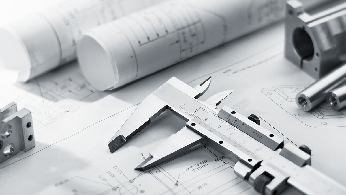
The flatness of a machine tool is the key to geometric accuracy, and a level or collimator is generally used for measurement.
First, explain the definition of flatness and the measurement path of flatness, explain the definition of straightness, analysis method, and calculation method, then explain the case of flatness measurement, and finally explain what is the closed error of flatness. It is expected that the industry can establish correct measurement concepts and effectively improve the accuracy of existing machine tools, and enhance the machine's international competitiveness.
The installation standard surface of the machine tool or the guide surface of linear motion is a flat shape, so the flatness requirements for component assembly and movement accuracy are more important. The high-precision machine tool not only improves the quality of the machine tool but also maintains it. Longer service life.
According to ISO 1101 product geometric specifications and ISO 230-1 geometric accuracy specifications of machine tools under no-load or finishing conditions, the flatness is defined as "the size of the mechanical geometric plane deviation" which means that the flatness is defined as virtual upper and lower Two parallel planes cover the smallest distance between the two planes, which is called flatness.
There are infinite points on the actual plane. Therefore, if the flatness is tested according to this definition, the amount of data is huge and the actual test will be difficult. Therefore, in reality, multiple straight nesses are combined to form a plane, and finally, error calculation and analysis are performed. There are two main types of measurement paths for plane measurement: (1) U-JACK (or rice character, diagonal). (2) Grid (or square grid).
When the workbench is small (such as 1000 mm x 1000 mm or less), no matter what measurement method is used, the error is similar, but for large-size platforms (such as large gantry models above 4000 mm x 2500 mm) using U-JACK does not measure There are many locations, and the overall flatness error is less objective.
Therefore, the current ISO standards such as ISO 10791 cutting center machine specifications and ISO 8636 gantry machining machine specifications all recommend the use of the grid method for inspection.
Based on experience, it is known that inspecting large workbenches (such as 4000 mm x 2500 mm, with a span of 500 mm) is very time-consuming and cannot be done by a single person. Therefore, it is recommended to use the U-JACK path measurement to confirm the specifications during the initial flatness verification of large-scale machine tool assembly, and finally perform the grid method verification, which can improve the efficiency of machine tool assembly and accuracy acceptance control.
Straightness
Straightness is the amount of change of the actual line (path) to be measured to the ideal straight line. There are three common analysis methods, namely End Point fitting, Regression, and Minimum Zone Method. The three methods are the easiest to calculate with the zero-return method at both ends. However, the least square method and the area method need to use software for analysis and calculation due to their complicated calculations.
The correction line of the two-end point return method is represented by a reference straight line that passes through the first point and the last point of the measurement work. It is the measured straight-line data minus the correction line to generate a new straight line for degree data, the measured value of the first and last point on the straight line will be reset to zero.
When using the least square method to calculate straightness, it subtracts this regression correction line from the measured straight-line data to generate new straightness data. The center line is represented by a straight line parallel to the measuring axis.
The area method is the ISO 1101 standard analysis method, which is two parallel lines that can cover all the measured values and the distance between the two lines is the smallest.
Commonly used inspections for straightness are level gauges and collimators. The measured values are all angle errors. The customary unit of machine tools for small angles is arc-sec. The angle unit is a 60-bit system, which is 1 degree. It can be divided into 60 minutes, and 1 minute is divided into 60 arc seconds, so 1 degree = 3600 arc seconds.
The other angle unit is the slope (mm/M). The measurement scale used by the traditional bubble level is the slope unit; the measurement resolution of the general bubble level is 0.02/M, and the corresponding angular seconds can be obtained through conversion. The unit is 0.02 mm/1m≒4arc-sec. Straight-line measurement needs to meet the following three conditions:
- The measured value of the tiny angle of each step (by the measuring instrument decided).
- The length of each step (the contact length between the fixture and the surface to be measured degree).
- The interrelationship of each step distance (two points of chain law).
For the first point, the measuring instrument determines the angle error value. For the second point, the length of each step can refer to Figure 8. If the collimator is used for measurement, the flat mirror fixture set module must be regarded as a fixed span. Distance length, which is the basis for calculation.
The angle error is used to convert the straightness with a fixed interval. If the span is assumed to be the hypotenuse, the displacement change is Lsinθ, and Lθ can also be calculated directly with the chord length. Since the angle error is small, Lsinθ≒Lθ.
The interrelationship of each step of point 3 means that all measurement modes must comply with the end-to-end connection, and the chain method can be used to measure the error of the object to be measured.
Taking a collimator measurement case to illustrate, the mirror span is 103.5 mm and its total measurement length is 1242 mm. Through the measurement, the angle error of each line segment (arc-sec) can be obtained. The relative height can be calculated by H=Lsinθ. The degree is a continuous error, so it is necessary to calculate the cumulative height difference and then obtain a continuous curve. Finally, through the two-point zeroing method, the front and back data is zeroed after subtracting the slope error, and the representative line of the two-point zeroing method is obtained.
The inspection method of the level gauge is explained: through the characteristic of keeping the bubble at the highest position, the machine tool can be checked whether the machine tool is in an absolute horizontal state and the inspection angle change; the measurement is based on the nearest and easy-to-read baseline, and the chain method is used to measure each Measure the inclination of the line segment, and then connect the line segments to obtain a continuous curve (cumulative displacement), which is the straightness.
Flatness
When performing flatness inspection, it is necessary to ensure the absolute level of the surface to be measured to avoid the impact of an unbalanced machine tilt on accuracy. Place the level meter on the work surface to be calibrated to ensure that the value of the level meter 0 degrees and 180-degree position is the same, it's recommended to adjust to within 0.050 mm/M.
Assuming that the level is adjusted well, within 0.050 mm/m (its flatness is zero), the answers obtained at this time will be similar regardless of the position of the level. Assuming that the level is not adjusted well, beyond 0.050 mm/m (the flatness is zero), the answer will vary greatly at this time, so it is more important to adjust the reference plane well. If the absolute level is below 0.050 mm/m.
In the above situation, you must first draw parallel lines and use a parallel straight ruler to keep the level meter straight to eliminate the level error.
The current international trend is mainly the ISO standard grid method for measurement. The grid method is equally distributed on the measuring surface, and the straightness is obtained along each measuring line, and finally, the overall flatness of the surface is obtained from the straightness. Take a square platform as an example: evenly distribute the X and Y spacing lengths and then measure and record the error.
Closure error
The so-called closed error is an indicator of the flatness measurement quality. When using different paths to calculate the height at the measurement point, the closing error refers to the maximum deviation of the measurement point in the grid. The sources of closed errors are as follows:
- The temperature difference between the level gauge and the surface to be measured (not the same temperature).
- Change the original measurement position or the influence of vibration.
- The measurement is not performed following the correct procedures.
- The surface to be measured or the bottom surface of the spirit level is dirty.
- Capture record data before the instrument is stabilized (stabilization time is insufficient).
- The travel distance is not correctly connected end to end (slightly overlapping).
- The planned grid path is incorrect.
- Measure the wear and deformation of the base.
- Poor repeatability of shaking of the measuring base.
Generally, the closing error cannot exceed 20%~25% of the maximum flatness error. If it exceeds, it should be confirmed whether the source of the closing error is eliminated.
Establish correct measurement concepts to improve machine accuracy
First, the definition of flatness and the measurement path of flatness, then the definition of straightness, analysis methods, and calculation methods are introduced, and then the case of flatness measurement is explained, and the source of closed error is explained. The closed error must be within a maximum error of 20% ~ 25%. The flatness of the worktable is the basis of geometric accuracy and the accuracy of assembly, such as the parallelism of the X-axis/Y-axis movement between the spindle and the worktable, the perpendicularity of the spindle axis and the worktable, and the XY plane, XZ The perpendicularity of the plane and YZ plane, the above items all have a mutual relationship with the flatness, so it has a great influence on the geometric accuracy of the overall machine tool.