Find the Real Production Bottleneck Before Choosing Automation
Buying a large 5 axis universal machining center is not simply a question of travel size, spindle speed, or whether the machine can machine five sides in one setup. For many factories, the more important question is this: What is actually slowing down production today?
A large machining center may reduce setups, improve access to complex surfaces, and support bigger workpieces. But the expected productivity gain can disappear if operators still spend too much time waiting for cranes, loading fixtures, moving parts between stations, checking orientation, or transferring workpieces to the next process.
This is why an automation upgrade should begin with the production problem, not with the phrase “full automatic.”
Some factories mainly lose time at the machine door. The CNC cycle is stable, but an operator must repeatedly load raw material, remove finished parts, and restart the next cycle. In this case, a loading and unloading automation cell may be the most practical investment.
Other factories have a broader problem. A workpiece may travel through several machining, inspection, cleaning, or assembly stations. It may need to be manually repositioned, re-clamped, or transferred by forklift between each step. In this situation, automating only one machine may improve one operation while leaving the overall line bottleneck unchanged.
The right large CNC universal machining center and automation architecture should therefore be selected together. The goal is not to buy the most automated machine. The goal is to remove the constraint that limits throughput, quality, labor availability, or delivery reliability.
Start With the Production Constraint, Not the Equipment Name
A large machining center is often purchased because production demand has increased, part geometry has become more complex, or existing machines require too many setups. These are valid reasons. However, the buying team should first identify where time, labor, and variation are being lost.
Track one representative product family for several production cycles. Record the time spent in each activity:
- Waiting for material or a fixture
- Loading and unloading the workpiece
- Setting the workpiece datum
- Machining
- Tool changing
- Inspection
- Moving the part to the next process
- Correcting errors, rework, or waiting for approval
This simple observation often reveals that the longest delay is not cutting time.
For example, a large aerospace part may require a long CNC cycle, making automatic loading less critical than reliable machining accuracy and unattended cutting. A tire mold, pump component, or heavy aluminum workpiece may have a shorter cycle but require repeated handling. In that case, loading and unloading can become the main source of lost capacity.
A purchasing decision should connect the machine investment to a measurable operating problem:
| Production problem |
Likely first priority |
Typical solution direction |
| Operators wait at the machine door between repeatable cycles |
Reduce manual loading and unloading |
Machine-tending cell with robot, gantry, pallet, or handling device |
| Workpieces repeatedly move between machining stations |
Reduce station-to-station handling |
Integrated transfer architecture with carriers, conveyors, AGVs, or pallet systems |
| Many setups create alignment errors and long lead times |
Complete more surfaces in one clamping |
Large 5 axis universal machining center with suitable rotary table and universal head |
| Heavy parts require difficult or unsafe handling |
Improve lifting, clamping, and workpiece access |
Automated handling, safety design, fixture review, and load-capacity verification |
| Product mix changes often |
Preserve flexibility and fast changeovers |
Modular automation and standardized workholding |
| Tool wear or thermal drift affects quality |
Stabilize machining performance |
Thermal compensation, probing, adaptive control, and process monitoring |
The key principle is simple: choose an architecture based on the part flow and the source of lost time, not based on which equipment description sounds more advanced.
Two Automation Architectures for Large CNC Machining
The most useful comparison is not “manual versus automatic.” It is between two different automation scopes.
Architecture 1: Machine-Tending Automation
Machine-tending automation focuses on one machining center or a small group of closely related machines. A robot, gantry, pallet changer, loading station, or handling device supplies workpieces to the CNC machine and removes them after machining.
This architecture is usually appropriate when the machining center itself is the main constraint and the incoming and outgoing material flow is already manageable.
A machine-tending system can reduce repetitive manual handling and support longer unattended periods. It may also improve consistency in workpiece placement when part geometry and fixtures are standardized.
However, it does not automatically solve problems beyond the machine. If parts still wait for inspection, require manual transfer to a second machine, or arrive without a consistent carrier, the automation island may operate efficiently while the wider process remains fragmented.
Architecture 2: Fully Integrated Transfer-Line Automation
A fully integrated architecture connects multiple processes. Workpieces move from one station to another through defined carriers, pallets, conveyors, rail-guided systems, automated guided vehicles, or other transfer methods. The system may link machining, washing, measurement, marking, assembly, and storage.
This approach is more suitable when manual movement between operations is a major source of delay, damage risk, traceability gaps, or inconsistent queue management.
It can create a more continuous material flow, but it requires greater preparation. Product routing, carrier design, fixture interfaces, machine communication, safety zones, and exception handling must all be defined before commissioning.
The comparison below helps teams distinguish the two approaches.
Before selecting either option, map the workpiece path from raw material to finished part. Do not map only the CNC machine cycle.
| Decision factor |
Machine-tending automation |
Fully integrated transfer-line automation |
| Automation scope |
One machine or compact cell |
Multiple machines and process stations |
| Main problem solved |
Repetitive loading and unloading |
Manual transfer and disconnected process flow |
| Manual handling |
Reduced at the machine |
Reduced across the full process route |
| Carrier movement |
May be simple or limited |
Usually essential and standardized |
| Upstream and downstream integration |
Often optional |
Central to system performance |
| Initial complexity |
Lower |
Higher |
| Changeover flexibility |
Often stronger for mixed production |
Depends on carrier, fixture, and routing standardization |
| Future expansion |
Add machines or handling modules gradually |
Expansion requires planned physical and control interfaces |
| Best fit |
Stable machine cycles with a localized labor bottleneck |
Repetitive multi-station production with frequent inter-process movement |
Neither architecture is universally better. A fully integrated line can be excessive for high-mix, low-volume work with frequent engineering changes. A machine-tending cell can be too limited when operators spend more time transferring parts between stations than loading the CNC machine itself.
Five Questions to Answer Before Choosing Automation Scope
A good automation decision can be made more clearly when the team answers a small set of operational questions with real data.
1. How Many Manual Handling Points Exist Per Part?
Count every point where a person, forklift, hoist, or crane must move the workpiece. Include transfers between machining, inspection, cleaning, deburring, and storage.
One loading point per part may support a machine-tending solution. Five or six handling points usually suggest a broader process-flow problem.
Also record part weight, lifting method, and the risk of damage. A large workpiece that must be turned or re-clamped by hand introduces both safety and quality risks.
2. Does the Workpiece Need Station-to-Station Transfer?
If one 5 axis universal machining center can complete the majority of machining in a single setup, station-to-station transfer may become less important. This is one of the strongest reasons to consider five-axis capability for complex, high-value parts.
But some processes cannot be consolidated. A part may still need heat treatment, washing, CMM inspection, special finishing, or assembly. If these processes occur in a fixed, repeated sequence, a defined transfer system may be justified.
The question is not whether automated transfer is technically possible. The question is whether manual transfer is causing enough delay, variation, or safety exposure to justify it.
3. Is the Existing Line Standardized Enough to Automate?
Automation performs best when the inputs are predictable.
Before connecting multiple stations, confirm that the factory has consistent standards for:
- Workpiece orientation
- Datum surfaces and clamping positions
- Fixture interfaces
- Pallet or carrier dimensions
- Part identification and routing
- Tool-life management
- Quality acceptance rules
- Machine alarms and recovery procedures
If each operator uses a different setup method, or if parts arrive with variable orientation, a larger automation system may reproduce confusion faster rather than improve output.
For this reason, standardization is often the first automation project. Documenting the process, simplifying fixture designs, and creating common carrier rules may provide more value than immediately adding transfer equipment.
4. What Happens When Something Goes Wrong?
A purchasing specification should include normal operation and abnormal operation.
Ask how the system responds if a workpiece is missing, incorrectly positioned, damaged, or out of tolerance. Ask what happens when a tool reaches its wear limit, a machine stops, a carrier is unavailable, or an inspection result fails.
The required answer is not “the system will stop.” The required answer is a recovery method that allows the factory to identify the problem, protect people and equipment, and restart production without losing traceability.
This is especially important for large, expensive components where one incorrect movement can cause costly damage.
5. What Must Be Easy to Expand in Three Years?
Production requirements rarely remain unchanged. A supplier should be asked whether the proposed system can later add a second machine, extra pallet positions, more tools, probing, inspection integration, or production data connectivity.
A modular machine-tending cell may offer a lower-risk first step. A full transfer architecture may be the better choice when volume, routing, and product design are already stable enough to justify a long-term line layout.
The right answer depends on the confidence of the demand forecast and the maturity of the process.
Core Machine Factors When Buying a Large 5 Axis Universal Machining Center
Automation cannot compensate for a machining center that does not fit the workpiece, material, or required accuracy. Once the automation scope is clear, evaluate the machine itself against the actual production need.
Work Envelope, Table Load, and Part Access
Start with the complete workpiece and fixture, not the raw part drawing. Include clamping height, tool length, clearance during B/C-axis movement, and access for loading equipment.
A machine with sufficient X, Y, and Z travels can still be unsuitable if the rotary table cannot carry the fixture and workpiece safely or if the universal head cannot reach key surfaces without collision risk.
For large components, table load distribution matters as much as maximum load. An off-center workpiece may affect rotary performance, fixture rigidity, and accuracy. Ask the supplier to review the planned workpiece model, fixture concept, center of gravity, and machining orientation.
Five-Axis Kinematics and Collision Prevention
A 5 axis universal machining center should create value by improving access and reducing setups. The practical benefit is not simply that the machine has five axes. It is that the machine can reach complex features while maintaining favorable tool angles and reducing repeated re-clamping.
Review the kinematic layout with the actual part program or simulation. Check for:
- Reach to deep or angled features
- Clearance between head, tool, fixture, and workpiece
- Rotary-axis limits
- Cable and hose management
- Tool-center-point control
- Collision detection or simulation capability
- Safe positions for loading and unloading
A machine that looks capable in a brochure may require difficult repositioning if its rotary configuration is not suitable for the target part family.
Accuracy, Repeatability, and Thermal Stability
For complex parts, machine accuracy should be evaluated as a process, not as one catalog number.
Positioning accuracy indicates how close an axis can move to a commanded location. Repeatability indicates how consistently it returns. Thermal behavior matters because long machining cycles, spindle heat, ambient temperature changes, and moving machine structures can affect dimensional results.
Ask for acceptance conditions, measurement methods, and the machine configuration used for the stated performance. Consider whether the application needs linear scales, spindle cooling, structure thermal compensation, in-process probing, or automatic tool measurement.
These options should be linked to a real quality risk. For example, if a part requires precise relationships between features machined on different faces, repeatable rotary performance and thermal control may be more important than peak rapid-traverse speed.
Spindle, Tooling, and Chip Control
Spindle selection should reflect materials, cutter diameters, torque requirements, and finishing needs. High spindle speed can be valuable for aluminum and small tools, while torque and rigidity may matter more for heavy cutting.
Do not specify spindle speed in isolation. Review the planned cutting conditions, toolholder type, through-spindle coolant requirement, magazine capacity, and the effect of chips on unattended production.
Long, unattended cycles need dependable chip evacuation and coolant management. Chip buildup can interfere with fixtures, probing, machine movement, and automatic loading. This makes conveyor design, coolant filtration, roof flushing, and access for maintenance part of the automation decision.
Controls, Data, and Maintainability
A machining center is also a data source. The control system should support the programming methods, post-processors, simulation, and operator skills used by the factory.
For an automated cell or line, the machine must exchange meaningful status information with handling equipment and production systems. At minimum, the project should define machine-ready, cycle-start, cycle-complete, alarm, safety, and workpiece-identification signals.
Maintenance access matters too. A system that is difficult to clean, inspect, or recover after an alarm may reduce availability despite having more automation.
The International Federation of Robotics notes that robot-market data and case studies are useful for assessing automation, but every installation still requires application-specific analysis of costs, output, and operating conditions. This is why a realistic cycle-time and recovery-time review is more valuable than a generic return-on-investment claim.
A Practical Supplier Evaluation Checklist
Before issuing a purchase order, ask each supplier to respond to the same application brief. This makes technical comparisons more meaningful.
Include the following items:
- Part drawings, materials, annual volume, batch size, and future product variations
- Finished-part quality requirements and critical dimensions
- Workpiece and fixture weight, center of gravity, and lifting restrictions
- Existing cycle time, setup time, loading time, and handling time
- Required machining operations and number of setups today
- Target unattended operating time
- Upstream and downstream processes that require integration
- Planned workholding, pallets, carriers, and identification method
- Required safety standards for the installation country
- Utility requirements, foundation conditions, and available floor space
- Commissioning, operator training, service response, and spare-parts expectations
- Expansion options for future machines, pallets, tools, or inspection stations
Safety must be designed into the project rather than added at the end. Machine guarding should protect operators from hazards associated with points of operation, rotating parts, chips, and other machine-area risks. For automated systems, review guard access, interlocks, emergency-stop zones, safe recovery procedures, and the interface between material handling and the CNC enclosure.
Where VISION WIDE Fits in a Large-Part Automation Plan
VISION WIDE TECH CO., LTD. is a Taiwan-based CNC machine tool manufacturer offering machining solutions from heavy cutting to high-speed machining, including five-axis equipment for industries such as vehicle manufacturing, power generation, and aerospace components.
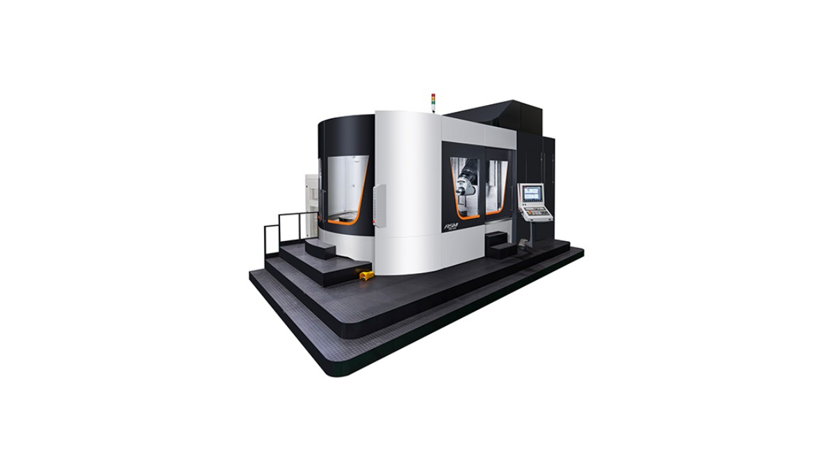
For factories assessing a large 5 axis universal machining center, the VISION WIDE ASM/ASM-FD Series is designed for five-axis turning and milling of cylindrical and complex components. Published series specifications include X-axis travels from 1,000 mm to 1,620 mm, table diameters from Ø1,000 mm to Ø1,500 mm, and maximum central table loads up to 3,000 kg, depending on the model.
The series also lists features relevant to automation and process stability, including thermal compensation, dynamic collision monitoring, linear scales on the X/Y/Z axes, remote monitoring software, and optional automatic workpiece and tool measurement. These features should be assessed against the buyer’s own part, fixture, cycle time, and integration plan rather than treated as universal requirements.
A productive discussion with a machine-tool supplier begins with the production map described above. When the supplier understands where loading, transfer, setup, or accuracy is limiting output, the proposed machine configuration can be matched to the real manufacturing case.
FAQ
Is a fully automatic production line always better than a loading and unloading cell?
No. A loading and unloading cell can be the better choice when the primary bottleneck is repetitive handling at one CNC machine. A fully integrated line is more suitable when manual transfer between several stations is the main source of lost time, inconsistency, or safety risk.
What should I check before buying a large 5 axis universal machining center?
Check the full workpiece and fixture envelope, table load and center of gravity, spindle and tooling needs, five-axis reach, thermal stability, chip control, control compatibility, and the expected integration with loading, inspection, and downstream processes.
How do I know whether my process is ready for transfer-line automation?
Your process is more ready when workpiece orientation, fixtures, carriers, routing, quality criteria, and recovery procedures are standardized. If these vary by operator or batch, improve standardization before expanding automation scope.
Can a five-axis machining center reduce the need for station-to-station transfer?
Often, yes. When more surfaces can be machined in one clamping, the number of setups and transfers may decrease. However, external processes such as washing, inspection, heat treatment, or assembly may still require a defined material-handling plan.
What information should I give a CNC machine supplier?
Provide representative part drawings, materials, production volume, batch size, target cycle time, workpiece and fixture weight, quality requirements, current process route, available floor space, and the specific production bottleneck you want to remove.
Choose the Architecture That Solves the Actual Problem
The best large CNC investment is not defined by the number of automated features. It is defined by whether the machine and automation architecture remove the constraint that is holding production back.
If the problem is repeated loading and unloading, prioritize dependable machine tending. If the problem is manual movement across several processes, evaluate integrated transfer. If setups and access are the problem, a properly configured 5 axis universal machining center may reduce handling before additional automation is even required.
Contact VISION WIDE Experts for 5 axis universal machining center Solutions and discuss your workpiece, fixture, current process flow, and future automation plan before specifying the machine.

(4059)(20260924)(原).jpg)
(2367)(20260924)(原).jpg)