What Is CAD?
Knowledge

What Is CAD?

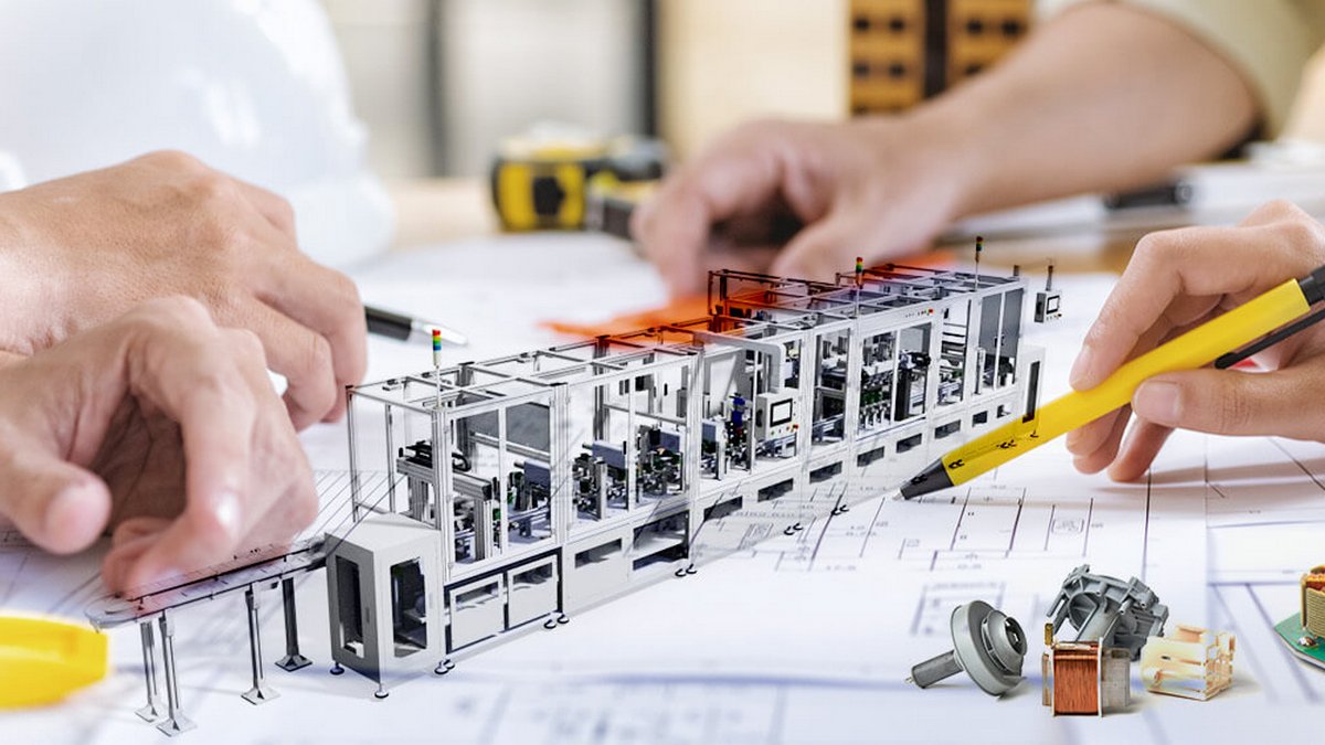
Today we are talking about CAD. Computer-aided design (CAD) is the use of computers (or workstations) to aid in the creation, modification, analysis, or optimization of a design.
Published: Jul 07, 2020
What Is CAD?

What is CAD?

Generally, there are two definitions of computer-aided design (CAD):

Computer-aided drawing:

Send all the data or sketches from the design to the computer system, and after processing, get the various engineering drawings required for manufacturing. The data on the engineering drawings generated by input or processing can be sorted and organized to form a database. In order to modify the drawing, it can also be exported in various forms for manufacturing and processing.

Computer-aided design:

Enter various specifications and conditions required by the design into the computer system, and use the design method organized in the database and the required data (such as material properties) to calculate or make decisions. Finally get various engineering dimensions and processing procedures and so on. Computer-aided design sometimes includes simulation. It is about to design the model (software model), and test its performance directly in the computer to check whether the design has a problem. Simulation can save the cost of physical testing, and can also help the best design, that is, calculate the best size and find the best processing program under the required specifications and conditions.

At present, the CAD system still focuses on computer drawing, drawing and solid simulation. Therefore, the CAD system mostly uses its drawing ability as a classification standard. The following briefly introduces the existing several systems.

Two-dimensional drawing (2D):

The software of the 2D system imitates the drawing of the projected image. Generally simple graphics, input from the CAD machine of the 2D system is not time-saving than drawing on the drawing table, but if some parts or components appear more often, CAD can save a lot of drawing time. Especially in the flexible production system, small-scale batch production, often used many standard parts, this time 2D system is a very effective tool. The drawing system stores all relevant data of all components and parts in the memory of the computer. In order to facilitate access and classification, the system includes a database. Newly built components or components can also be modified and stored by the original components or components.

If CAD machines of different brands are to be used in conjunction with each other, the interface is a big problem, even experts have a headache.

Choose two-dimensional drawing:

The same as 2D, it also expresses the graphics of the x-y plane. However, it is more advanced than 2D, and you can choose the z coordinate position of the image to be represented. Users can choose different z-coordinates, that is, choose different projection planes (sections) for projection. At the same time, they can also change the direction of projection to get different angles of view. Projections of different z coordinates are often added with different colors.

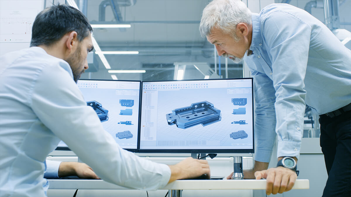
Three-dimensional drawing (3D):

It can express three-dimensional graphics (outline ridge diagram) on a plane. 3D software can provide rotation of objects. (You must enter enough point and line data beforehand) Some 3D system software can calculate the volume, weight, moment of inertia and center of gravity of the object. (The system must have enough data to determine which part is hollow and which part is solid.)

The more irregularly shaped the object, the more ridges it has, and the more ugly the 3D graphics are. Therefore, the software of the 3D system must have a coloring method, so that different types of wires have different colors to achieve a clear visual effect. When actually looking at objects, some ridges are invisible, so these issues must be taken into account when designing the software. Different dots and lines must be hidden at various angles. Another software technique is called layering. When the configuration graph representing a plane is too complex, the configuration can be divided into several graphs for easy identification. For example, arrange all screw holes and screws on one drawing, and arrange other configurations on other drawings.

Surface Modelling:

More advanced than 3D system. The soft model of the object is composed of the various surfaces that make up the outline. The system software can help coloring on different surfaces. Like the 3D system, objects can be viewed from different angles, and lines and surfaces that are invisible to real objects can be hidden. Of course, the color of each line and each surface cannot be affected by the rotation of the object. Some systems can calculate the luminosity and shadow of each position of the object (the position of the light source must be given first), so that the resulting picture is closer to the real object.

Solid Modelling:

The body model can be said to be a physical prototype of the designer's software. The biggest difference between the volume model system and the aforementioned systems is the use of visual projection (perspective) rather than the parallel projection used in general engineering drawings. Therefore, the picture you see can be exactly the same as the actual object. The volume model system can still provide cross-sectional views at different positions. Although the 3D system can profile, it can only represent point lines, and there is no function of the surface model. The volume model is based on the position of the point and the properties of each position to establish the model, so you can calculate the physical quantities of the entity without entering additional data.

At present, this system is too expensive, so only the aviation industry uses this system. Because airplanes and space vehicles must save as much weight as possible, the design, simulation, and inspection requirements are very high, and they will not hesitate to invest huge costs.

The processing speed of the body model system is not fast. If you want to have the same processing speed as the 3D system, its computing power must be ten times stronger than the 3D system. The body model system has a big advantage, it can do physical fit (fit) experiments. After the components are designed, you can do assembly experiments on the terminal. The software structure of the body model is very suitable for the design of the simulation program. If the assembly is found to be incompatible, the design can be modified in time.

Published by Jul 07, 2020 Source :resource.blsh.tp.edu.tw Source :pcschool.com.tw

Further reading

You might also be interested in ...

Headline
Knowledge
Essential for Precision Machining: A Complete Guide to Tungsten Carbide Center Drills
In modern manufacturing, precision is the core standard by which product quality and performance are measured. From aerospace components to medical devices, even a minor deviation can lead to serious consequences. When it comes to precision drilling, a critical challenge is ensuring that a drill bit can be accurately positioned at the start of a cut while maintaining stability during high-intensity operations. The tungsten carbide center drill is the professional tool engineered specifically to solve this problem.
Headline
Knowledge
From Cavitation Effect to Industrial Applications: The Secrets of Ultrasonic Cleaning
When your glasses, tableware, or electronic components are stained with stubborn dirt, what can you do? Traditional methods often require vigorous scrubbing or even harsh chemical solvents, which are not environmentally friendly and may scratch the item. At this moment, ultrasonic cleaning acts like an “invisible little helper”, reaching deep into grooves and gaps to gently yet effectively remove contaminants.
Headline
Knowledge
The “Spark Magician” of Metalworking
Electrical Discharge Machining (EDM) is a non-traditional machining process that removes metal through electrical sparks. Unlike conventional methods, it is not limited by material hardness and can precisely create deep cavities, micro-holes, and complex structures in hardened steel, tungsten carbide, or superalloys. The three main types of EDM include wire cutting, die-sinking, and hole drilling, which are widely applied in mold making, aerospace, automotive, and medical industries. Although EDM has a slower processing speed, works only with conductive materials, and requires consideration of electrode wear and surface treatment, its advantages in high precision, zero cutting force, and superior surface finish make it an indispensable technology in precision manufacturing. Moreover, it continues to evolve in line with the trend toward smart manufacturing.
Headline
Knowledge
Press Brake vs Shearing Machine: Functional and Technical Comparison of Industrial Processing Equipment
Press Brake and Shearing Machine are two essential types of equipment in the field of machine tools, widely used in the processing of metal, wood, and other materials. They play critical roles in manufacturing, enabling efficient and precise material forming and cutting. This article introduces the definitions, functions, technical features, and applications of folding and cutting machines, offering neutral and practical knowledge sharing.
Headline
Knowledge
Master Chuck Types & Selection: The Essential Guide for Machinists
In the world of precision manufacturing, every minute detail can determine the quality of the final product. The chuck is a critical yet often overlooked component—it's not just a tool for holding a workpiece, but the very heart of ensuring machining accuracy, efficiency, and safety. This article will take you on a deep dive into the diverse universe of chucks, covering their operating principles, design philosophies, common types, and how to select the right jaws and chucks for different needs. Whether you're new to the industry or a seasoned engineer, this guide will unlock the intricate secrets of chucks, helping you master every detail on your path to manufacturing success.
Headline
Knowledge
An Overview of Electrical Discharge Machining (EDM)
Electrical Discharge Machining (EDM) is a non-traditional manufacturing process that utilizes electrical sparks to remove material from a workpiece. Unlike conventional machining methods such as milling or turning, which rely on physical contact between a tool and the material, EDM operates without direct contact, making it ideal for processing hard or brittle materials that are difficult to machine otherwise. The process involves generating a series of rapid electrical discharges between an electrode and the workpiece, submerged in a dielectric fluid, which erodes the material through thermal energy. This technique has revolutionized precision manufacturing by enabling the creation of complex geometries with high accuracy.
Headline
Knowledge
Applications of Machine Tools in the Aerospace Industry
The aerospace industry is a highly specialized and technology-driven sector, encompassing the design, manufacturing, and maintenance of aircraft, spacecraft, satellites, and related equipment. Machine tools play a critical role in this field, enabling the precision machining of complex metal and composite material components. These tools enhance production efficiency while ensuring the accuracy and reliability required to meet the stringent safety and performance standards of aerospace. This document outlines the key applications, technologies, benefits, and future trends of machine tools in the aerospace industry.
Headline
Knowledge
Smart Healthcare Uncovered:How AI Is Transforming Clinical Practice?
With the rapid rise of artificial intelligence (AI), the healthcare industry is undergoing a disruptive transformation. AI is significantly improving diagnostic accuracy and treatment efficiency while profoundly redefining healthcare professionals’ roles and patient experiences. A comprehensive understanding of the core technologies and clinical applications behind this transformation is essential for grasping the future trends and strategic directions of smart healthcare.
Headline
Knowledge
Principle and Applications of Laser Cutting Machines
As the global manufacturing industry advances toward higher precision and efficiency, laser cutting technology has become a key enabler of industrial upgrading. Compared with traditional shearing, stamping, and mechanical cutting, laser cutting offers non-contact processing, higher accuracy, and greater flexibility. It significantly improves productivity while reducing secondary finishing. Today, it is widely adopted in metalworking and increasingly applied in electronics, aerospace, medical, and architectural design industries.
Headline
Knowledge
Why Are High-Quality Cutting Fluids Critical for Machining Quality?
In CNC and metalworking, cutting fluid is no longer just a coolant—it plays a critical role by providing lubrication, chip removal, and corrosion protection. With the right formulation and concentration, it can reduce cutting heat, minimize friction, extend tool life, and maintain workpiece accuracy. High-pressure cooling further enhances efficiency in deep-hole and high-speed machining. The pairing of tool material with the proper cutting fluid is equally crucial; correct selection and maintenance ensure process stability, prolong equipment life, and improve the overall work environment. Cutting fluid has become an indispensable investment in modern precision manufacturing.
Headline
Knowledge
Introduction to Emerging Printing Technologies: Opening New Horizons for the Future of Printing
With rapid technological progress and increasingly diverse market demands, traditional printing techniques are no longer sufficient to meet modern industry’s requirements for precision, efficiency, and sustainability. As a result, emerging technologies such as UV printing, 3D printing, and Nanoimprint Lithography (NIL) have risen to prominence, offering solutions with higher precision, broader applications, and lower production costs. These innovations have already demonstrated value across packaging, advertising, healthcare, semiconductors, and construction. In the following sections, we will explore their technical features and real-world applications, highlighting the advantages and future potential of these cutting-edge printing technologies.
Headline
Knowledge
The Core Standard for Life-Critical Systems: A Complete Guide to IPC Classification
In high-risk fields such as medical, aerospace, and automotive, IPC classifications determine PCB reliability and safety. Class 3 represents the highest standard, requiring zero tolerance for defects, complete via filling, adequate copper annular rings, and rigorous inspections to ensure operation under extreme conditions, while Class 2 suits long-term use in non-critical equipment with minor cosmetic flaws allowed. Class 3’s strict criteria cover component placement, soldering, plating thickness, and environmental testing—adding cost and production time, but far outweighing the risks of failure in life- or safety-critical systems. Thus, defining high-risk equipment as Class 3 during design is essential, making IPC classification a core safeguard rather than an option.
Agree