How electrode geometry, discharge behavior, flushing, and process settings influence wear patterns and dimensional accuracy in die-sinking EDM.
Die-sinking electrical discharge machining (EDM) can reproduce complex cavities in electrically conductive materials without direct cutting contact. Yet the electrode is not a permanent “negative” of the cavity. Every discharge can erode both workpiece and electrode, and that wear is rarely uniform. Corners round off, narrow ribs shorten, edges recede, and deep features may wear differently from open surfaces. EDM itself relies on electrical discharges between an electrode and workpiece separated by a dielectric medium.
This matters because electrode wear becomes a geometry problem: once the tool shape changes, the cavity it produces changes with it.
Why EDM Electrode Wear Is Uneven
In die-sinking EDM, repeated electrical discharges cross a small dielectric gap, creating intense localized heating followed by rapid cooling and material ejection. The electrode experiences the same environment, so some tool wear is unavoidable.
The sparks, however, are not distributed perfectly evenly. Local gap conditions, debris concentration, temperature, electrode material, polarity, pulse settings, and flushing all influence where discharges occur and how much energy reaches a given area. Research focused specifically on EDM corners and edges has shown that electrode wear can degrade the shape transferred to the workpiece, while electrode material and electrical parameters affect the severity.
Sharp corners are especially vulnerable. Their small local area can experience concentrated discharge activity, while the corner has less surrounding material to absorb and conduct heat than a broad face. As the corner erodes, it becomes rounded, so the electrode no longer reproduces the original shape exactly.
Geometry Changes Spark Behavior and Flushing
Electrode geometry does more than define the cavity. It also defines the gap through which dielectric fluid and debris must move.
A broad, shallow cavity usually allows relatively easy fluid exchange. A deep slot, thin rib, blind pocket, or enclosed detail can trap eroded particles. When debris accumulates, the gap becomes less uniform electrically, encouraging unstable discharges or arcing and sometimes forcing the control to reduce effective machining intensity until the gap clears. Reviews of EDM research consistently identify dielectric flushing as an important process variable.
Modern sinker EDM systems therefore use jump cycles, adaptive control, orbiting, and related strategies to improve debris evacuation. Machine builders also link improved flushing and debris removal with lower electrode wear and more stable machining.
| Electrode feature |
Typical wear tendency |
Why geometry matters |
| Sharp outside corner |
Rounding or local recession |
Concentrated discharge activity and limited thermal mass |
| Thin rib or narrow fin |
End wear and dimensional loss |
Small cross-section and restricted flushing |
| Large flat face |
More uniform face wear |
Larger active area and easier heat spreading |
| Deep narrow feature |
Uneven end/side wear |
Debris is harder to remove |
| Rounded corner |
Often more stable |
Lower geometric concentration and smoother fluid movement |
Recent experiments on deep narrow grooves found that rounded-corner electrodes reduced wear and improved machining efficiency compared with sharp-corner electrodes under the tested conditions. That does not mean every electrode should be heavily radiused; it means unnecessary sharpness can carry a process penalty.
Material and Electrical Settings Still Matter
Geometry does not act alone. Copper and graphite, two common sinker EDM electrode materials, respond differently to thermal loading and pulse conditions. A 2020 study comparing corner and edge wear reported lower wear and better shape accuracy with graphite for its tested combinations, but this should not be treated as a universal ranking. Electrode grade, workpiece material, polarity, finish target, and generator technology all influence the practical choice.
Electrical parameters also alter wear. Higher discharge energy can increase removal rate but may also increase thermal stress on the electrode. Pulse-on time, pulse-off time, current, voltage, and polarity influence discharge stability and the balance between workpiece erosion and tool erosion. Because EDM is stochastic, the setting that minimizes wear is not necessarily the fastest or best for surface finish.
For this reason, many shops separate roughing and finishing. A roughing electrode can prioritize removal rate, while a finishing electrode preserves final size, corner condition, and texture.
Designing Around Uneven Wear
The practical objective is usually not zero wear, but predictable wear. Where the part allows, replacing mathematically sharp corners with controlled radii can improve robustness. Deep or narrow details also need an effective path for dielectric fluid and debris.
Electrodes can be intentionally undersized to account for spark gap and orbiting. Complex forms may benefit from multiple electrodes rather than asking one electrode to rough and finish every feature. Dedicated roughing and finishing electrodes make wear easier to control because each tool performs a narrower role.
Internal flushing holes or slots can improve debris removal in some geometries, but poor placement can leave unwanted residual columns or uneven bottom conditions. Research on slotted electrodes with internal flushing shows both the potential benefit and the geometric trade-offs.
Electrode inspection is also part of process control. If a critical corner has rounded before the final passes, no generator setting can restore the missing geometry. Checking wear between stages and applying appropriate compensation or replacement criteria helps prevent dimensional drift.
FAQ
1. Why do EDM electrodes wear more at corners?
Corners can experience concentrated discharge activity and have less material around them to absorb heat. Small losses also become visible quickly as corner rounding.
2. Does a sharp electrode always produce the sharpest cavity?
No. A very sharp corner may wear early and create a larger-than-intended cavity radius. A controlled radius can sometimes be more repeatable if the part specification allows it.
3. Is graphite always better than copper for low wear?
No. Graphite often performs well, but copper may be preferred for certain fine-detail or finishing requirements. The best choice depends on the complete EDM setup rather than electrode material alone.
4. Can poor flushing increase electrode wear?
Yes. Poor debris evacuation can destabilize the discharge gap and promote localized sparking or arcing. Better flushing generally supports more stable machining.
5. Does orbiting reduce electrode wear?
It can improve flushing and spread machining action, but results depend on cavity geometry and the programmed orbit. Dimensional and spark-gap compensation must also be correct.
6. Should one electrode be used for both roughing and finishing?
It can be, but critical cavities often benefit from separate electrodes. A fresh finishing electrode is more likely to preserve final geometry and surface requirements.
Conclusion
Uneven electrode wear in die-sinking EDM is an interaction between discharge physics and geometry. Sharp corners, thin sections, deep pockets, and restricted gaps create different thermal and flushing conditions, so they do not wear like large open surfaces. Material selection and generator settings matter, but geometry often determines where accuracy loss appears first.
The practical goal is controlled wear: design realistic corner geometry, provide adequate debris evacuation, separate roughing and finishing when needed, and verify critical features before the final burn.
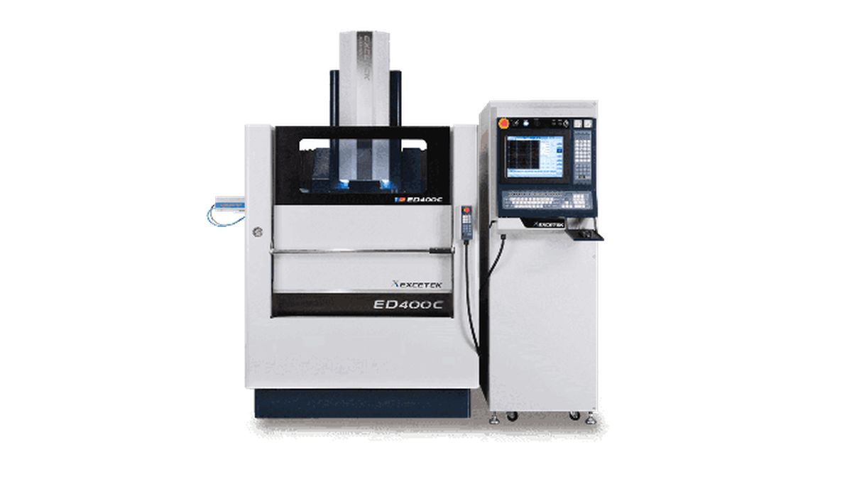
For readers comparing equipment for these applications, Excetek’s die-sinking EDM offers a useful starting point for reviewing available machine configurations and capabilities.

(4059)(20260924)(原).jpg)